Sharp R930AK Service Manual - Page 23
Touch Control Panel Assembly
 |
UPC - 074000606036
View all Sharp R930AK manuals
Add to My Manuals
Save this manual to your list of manuals |
Page 23 highlights
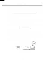
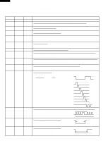
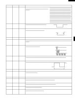
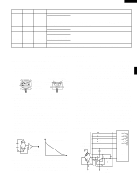
TOUCH CONTROL PANEL ASSEMBLY OUTLINE OF TOUCH CONTROL PANEL R-930AK R-930AW The touch control section consists of the following units as shown in the touch control panel circuit. (1) Key Unit (2) Control Unit The principal functions of these units and the signals communicated among them are explained below. Key Unit The key unit is composed of a matrix, signals P10 - P17 generated in the LSI are sent to the key unit. When a key pad is touched, a signal is completed through the key unit and passed back to the LSI through R24 - R27 to perform the function that was requested. Control Unit Control unit consists of LSI, power source circuit, synchronizing signal circuit, ACL circuit, buzzer circuit, temperature measurement circuit, absolute humidity sensor circuit and indicator circuit. 1) LSI This LSI controls the temperature measurement signal, AH sensor signal, key strobe signal, relay driving signal for oven function and indicator signal. 2) Power Source Circuit This circuit generates the voltages necessary for the control unit from the AC line voltage. 3) Synchronizing Signal Circuit The power source synchronizing signal is available in order to compose a basic standard time in the clock circuit. It incorporates a very small error because it works on commercial frequency. 4) ACL Circuit A circuit to generate a signals which resetting the LSI to the initial state when power is applied. 5) Buzzer Circuit The buzzer is responds to signals from the LSI to emit noticing sounds (key touch sound and completion sound). 6) Temperature Measurement Circuit : (OVEN THERMISTOR) The temperature in the oven cavity is sensed by the thermistor. The variation of resistance according to sensed temperature is detected by the temperature measurement circuit and the result applied to LSI. The LSI uses this information to control the relay and display units. 7) Absolute Humidity Sensor Circuit This circuit detects the humidity of a food which is being cooked, to control its automatic cooking. 8) Door Sensing Switch A switch to inform the LSI if the door is open or closed. 9) Relay Circuit To drive the magnetron, heating element, fan motor, convection motor, damper motor, turntable motor and light the oven lamp. 10) Indicator Circuit Indicator element is a Fluorescent Display. Basically, a Fluorescent Display is triode having a cathode, a grid and an anode. Usually, the cathode of a Fluorescent Display is directly heated and the filament serves as cathode. The Fluorescent Display has 8-digits, 16-segments are used for displaying figures. 21
-
 1
1 -
2
-
3
-
4
-
5
-
6
-
7
-
8
-
9
-
10
-
11
-
12
-
13
-
14
-
15
-
16
-
17
-
 18
18 -
 19
19 -
 20
20 -
 21
21 -
 22
22 -
 23
23 -
 24
24 -
 25
25 -
 26
26 -
 27
27 -
 28
28 -
29
-
30
-
31
-
32
-
33
-
34
-
35
-
36
-
37
-
38
-
39
-
40
-
41
-
42
-
43
-
44
 |
 |
