Sharp R930AK Service Manual - Page 31
Heating Element/convection Fan/convection Motor/thermistor - waveguide cover
 |
UPC - 074000606036
View all Sharp R930AK manuals
Add to My Manuals
Save this manual to your list of manuals |
Page 31 highlights
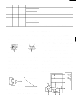
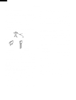
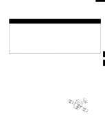
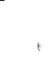
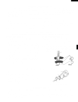
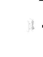
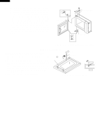
R-930AK R-930AW TURNTABLE MOTOR REMOVAL 1. Disconnect the oven from power supply. Remove the turntable tray, and the turntable support out of the oven cavity. 2. Turn the oven upside down and remove one (1) screw holding the turntable motor cover to the base plate and take off the turntable motor cover. 3. Disconnect wire lead from the turntable motor. 4. Remove the two (2) screws holding the turntable motor and coupling mounting plate to the oven cavity bottom. 5. Turntable motor, Coupling mounting plate and Thermal protection plate bottom will be free. DAMPER ASSEMBLY REMOVAL 1. Disconnect oven from power supply and remove outer case. 2. Discharge the high voltage capacitor. 3. Disconnect wire leads from damper motor and damper switch. 4. Remove two (2) oven side screws holding damper motor angle to thermal protection plate (right). 5. Damper assembly is free. 6. Remove one (1) screw holding damper motor to damper motor angle and one (1) screw holding damper switch to damper motor angle. 7. Damper motor and switch are free. HEATER UNIT ASSEMBLY REMOVAL (HEATING ELEMENT/CONVECTION FAN/CONVECTION MOTOR/THERMISTOR) THERMISTOR REMOVAL 1. Disconnect oven from power supply and remove outer case cabinet. 2. Discharge the high voltage capacitor. Disconnect wire leads from H.V. capacitor and remove four (4) screws holding rear cabinet to bottom plate and three (3) screws holding to heater unit assembly and two (2) screws holding steam duct to top of oven cavity. Disconnect wire leads from power supply cord terminals. 3. Disconnect wire leads from thermistor. Remove two (2) screws from thremistor. 4. Disconnect wire leads from convection motor, thermal cut-out and heater element. 5. Remove nine (9) screws holding heater duct to the oven cavity. 6. Remove two (2) screws holding heater duct to base cabinet. Release two (2) snap bands holding wire harness to the thermal cover (convection). 7. The heater unit is now free. HEATING ELEMENT REMOVAL 1. Remove two (2) screws holding heating element to heater duct. 2. Loosen two (2) screws holding holders to heater duct and take heating element out of heating element holders. 3. Heating element is free. NOTE: After installed the heating element completely, bent top of the heating element holder to inside using by long nose pliers as shown following illustration. Long nose plier Heating element Heating element holder OVEN LAMP AND LAMP SOCKET REMOVAL 1. Disconnect oven from power supply and remove outer case. 2. Discharge high voltage capacitor. 3. Bend the tab of the air guide holding the lamp socket. 4. Lift up the oven lamp socket. 5. Pull the wire leads from the oven lamp socket by pushing the terminal hole of the oven lamp socket with the small flat type screw driver. 6. Now, the oven lamp socket is free. Oven lamp socket Terminal Wire lead Terminal hole Flate type small screw driver Figure C-3. Oven lamp socket FAN MOTOR REMOVAL 1. Disconnect oven from power supply and remove outer case. 2. Discharge high voltage capacitor. 3. Disconnect the wire leads from the fan motor. 4. Remove one (1) screw holding the fan motor grounding wire to the air guide (Right). 5. Remove three (3) screws holding the chassis support to the rear cabinet, waveguide and control panel back plate. 6. Remove the chassis support from the oven. 7. Remove one (1) screw holding the magnetron air guide to the waveguide. 29
-
 1
1 -
2
-
3
-
4
-
5
-
6
-
7
-
8
-
9
-
10
-
11
-
12
-
13
-
14
-
15
-
16
-
17
-
18
-
19
-
20
-
21
-
22
-
23
-
24
-
25
-
 26
26 -
 27
27 -
 28
28 -
 29
29 -
 30
30 -
 31
31 -
 32
32 -
 33
33 -
 34
34 -
 35
35 -
 36
36 -
37
-
38
-
39
-
40
-
41
-
42
-
43
-
44
 |
 |
