Sharp TM200 Service Manual - Page 46
Disassembly And Reassembly
 |
View all Sharp TM200 manuals
Add to My Manuals
Save this manual to your list of manuals |
Page 46 highlights
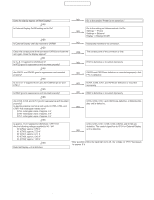
CONFIDENTIAL CHAPTER 3. DISASSEMBLY AND REASSEMBLY A. BATTERY REMOVAL 1) Remove the battery cover. 3) Remove the speaker from the cabinet B unit. * When installing the speaker, fit the speaker projection (a) with the concaved rib section. (a) 2) Remove the battery. C. VIBRATING MOTOR REMOVAL 1) Open the display section. Remove the screw cover, and remove the special screw. * When removing or installing the special screw, use the exclusive tool. * When tightening the screws, follow the tightening sequence of (a), (b), (c), and (d). (c) (a) B. SPEAKER REMOVAL 1) Open the display section. Remove the screw cover, and remove the special screw. * When removing the special screw, use the exclusive tool. * When tightening the screws, follow the tightening sequence of (a), (b), (c), and (d). (b) (a) (c) (d) (b) (d) 2) Disengage the pawls, and cabinet D unit. Remove the side key, the jack cover, and the external connector cover. 2) Close the display section. Disengage the pawls, and remove the cabinet B unit. 3) Remove the vibrating motor from the cabinet D unit. TM200 DISASSEMBLY AND REASSEMBLY 3 - 1
-
 1
1 -
2
-
3
-
4
-
5
-
6
-
7
-
8
-
9
-
10
-
11
-
12
-
13
-
14
-
15
-
16
-
17
-
18
-
19
-
20
-
21
-
22
-
23
-
24
-
25
-
26
-
27
-
28
-
29
-
30
-
31
-
32
-
33
-
34
-
35
-
36
-
37
-
38
-
39
-
40
-
 41
41 -
 42
42 -
 43
43 -
 44
44 -
 45
45 -
 46
46 -
 47
47 -
 48
48 -
 49
49 -
 50
50 -
 51
51 -
52
-
53
-
54
-
55
-
56
-
57
-
58
-
59
-
60
-
61
-
62
-
63
-
64
-
65
-
66
-
67
-
68
-
69
-
70
-
71
-
72
-
73
-
74
-
75
-
76
-
77
-
78
-
79
-
80
-
81
-
82
-
83
-
84
 |
 |
