Sharp TM200 Service Manual - Page 47
D. Backup Battery Removal, E. Main/lcd Pwb Unit Removal, F. Sub Lcd Removal
 |
View all Sharp TM200 manuals
Add to My Manuals
Save this manual to your list of manuals |
Page 47 highlights
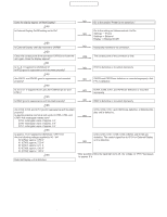
CONFIDENTIAL D. BACKUP BATTERY REMOVAL 1) Remove the backup battery from the main/LCD PWB unit. * When installing the battery, be careful of the installing direction and install it diagonally from the lower side of the battery holder spring. 2) Remove the camera shield case unit from the main/LCD PWB unit, and remove the camera flexible unit. Disengage the pawl, and remove the sub LCD unit. Disconnect the connector. E. MAIN/LCD PWB UNIT REMOVAL 1) Remove the ANT dust-proof sheet (a) and the submersion sheet (b), and remove the main/LCD PWB unit (c). (a) (c) (b) 3) Remove the connector (a). Disengage the pawl, and remove the main/LCD unit. Disconnect the connector (b). (b) * When attaching the ANT dust-proof sheet (a), fit it with the RF external antenna connector with the main/LCD PWB silk section as the reference. * When attaching the submersion sheet (b), attach it inside the bump area. (b) (a) (a) F. SUB LCD REMOVAL 1) Remove the sub LCD from the sub LCD holder unit. * Hold the both ends of the sub LCD as shown in the figure, and never press TAB (a). (a) * When attaching the PWB unit, rotate the main PWB and the LCD PWB 180 degrees in the arrow direction to wind the flat cable. TM200 DISASSEMBLY AND REASSEMBLY 3 - 2
-
 1
1 -
2
-
3
-
4
-
5
-
6
-
7
-
8
-
9
-
10
-
11
-
12
-
13
-
14
-
15
-
16
-
17
-
18
-
19
-
20
-
21
-
22
-
23
-
24
-
25
-
26
-
27
-
28
-
29
-
30
-
31
-
32
-
33
-
34
-
35
-
36
-
37
-
38
-
39
-
40
-
41
-
 42
42 -
 43
43 -
 44
44 -
 45
45 -
 46
46 -
 47
47 -
 48
48 -
 49
49 -
 50
50 -
 51
51 -
 52
52 -
53
-
54
-
55
-
56
-
57
-
58
-
59
-
60
-
61
-
62
-
63
-
64
-
65
-
66
-
67
-
68
-
69
-
70
-
71
-
72
-
73
-
74
-
75
-
76
-
77
-
78
-
79
-
80
-
81
-
82
-
83
-
84
 |
 |
