Sharp XE-A202 Service Manual - Page 10
Memory Circuit, Printer Control Circuit - driver
 |
UPC - 074000048270
View all Sharp XE-A202 manuals
Add to My Manuals
Save this manual to your list of manuals |
Page 10 highlights
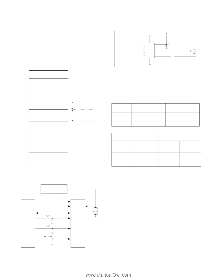
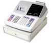
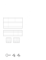
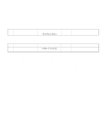
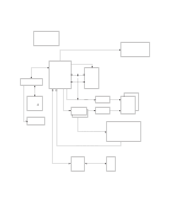
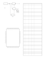
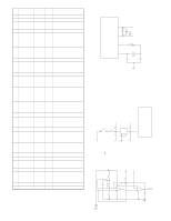
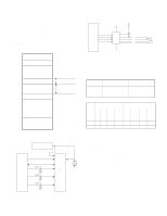
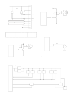
The P-OFF signal detects two signals by two comparators and sent to the CPU. V0 (24V) signal: If the power voltage V0 (24V) falls bellow the specified level, the P-OFF signal is driver to LOW by the comparator ICAA. VLED signal: If the LED/Logic power voltage VLED falls below the specified level, the P-OFF signal is driven to LOW by the comparator IC4B. 6. MEMORY CIRCUIT 1) Address map 00000h 00400h 05400h CPU internal RAM 20kbytes 06000h 08000h Segment latch address External S-RAM : 128kbytes 28000h (128kbytes area) 40000h /CS3 area 06000h - 07FFFh /CS2 area 08000h - 27FFFh C0000h FFFFFh CPU internal ROM 256kbytes 2) RAM control Power supply circuit or Dry battery A0-A16 A0-A16 D0-7 /CS2 CPU /RD VDD VCC D0-7 10K /CS2 150pF 10K /RD /WR 10K VCC /WR CS2 A0-A16 VCC I/O0-7 VDD 0.1M /CS1 11 S-RAM 128K byte IC /OE /WE 7. PRINTER CONTROL CIRCUIT 1) Paper feed motor circuit CPU VH VCC P14 10uF/50V P15 P16 IC13 A /A P17 B /B LB1838M MOTOR Stepping motor control The 2-phase, bi-polar stepping motor is driven at a constant voltage by LB1838M (made by SANYO). 1 step: 0.087mm 1 dot: 2 steps CPU port No. CPU port 76 P14 75 P15 74 P16 73 P17 Signal used IN1 IN2 ENA1 ENA2 Drive step Driver IC input (CPU output) Motor drive signal STEP IN1 IN2 ENA1 ENA2 A B /A /B (OUT1) (OUT3) (OUT2) (OUT4) 1 LL H H H H L L 2 HL H H L H H L 3 HH H H L L H H 4 LH H H H L L H 2) Print circuit Thermal head configuration As shown in the equivalent circuit in the figure, thermal head consists of heating elements and head drivers which drives and controls those heating elements. The serial print data input through the DATA IN (D1) is transferred to the shift register synchronizing with the CLOCK (CP) and stored in the latch register by the LATCH (LA) signal. The head conduction signals (print commands 1 ~ 6) turn the gate on to conduct the heating element corresponding to the print data. XE-A202U HARDWARE DESCRIPTION - 9 -
-
 1
1 -
2
-
3
-
4
-
 5
5 -
 6
6 -
 7
7 -
 8
8 -
 9
9 -
 10
10 -
 11
11 -
 12
12 -
 13
13 -
 14
14 -
 15
15 -
16
-
17
-
18
-
19
-
20
-
21
-
22
-
23
-
24
-
25
-
26
-
27
 |
 |