Sharp XE-A202 Service Manual - Page 13
Test Function
 |
UPC - 074000048270
View all Sharp XE-A202 manuals
Add to My Manuals
Save this manual to your list of manuals |
Page 13 highlights
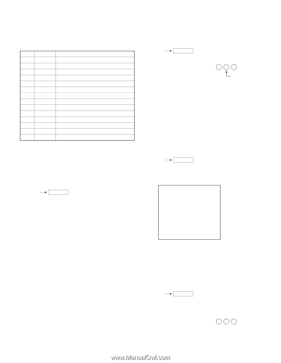
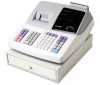
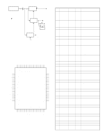
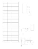
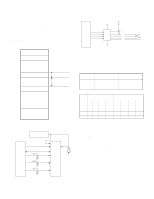
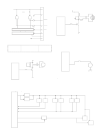
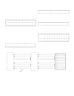
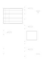
CHAPTER 5. TEST FUNCTION 1. TEST ITEMS The test items are as follows: NO. Code Description 1 100 Display buzzer test 2 101 Key code 3 102 Printer test 4 104 Keyboard test 5 105 mode switch test 6 106 Printer sensor test 7 107 Clock display test 8 110 Drawer 1 open & sensor test 9 120 External RAM test 10 121 CPU internal RAM test 11 140 CPU internal ROM test 12 160 AD conversion port test 13 500 RS232C test 14 550 Sleep mode test 2. DESCRIPTION OF EACH DIAGNOSTIC PROGRAM 1) DISPLAY BUZZER TEST 1 Key operation 100 RCPT/PO 2 Test procedure Display at operator side 1 . 2 . 3 . 4 . 5 . 6 . 7 . 8 . 9 . 0 . Display at front side 4.5.6.7.8.9.0. 2) KEY CODE 1 Key operation 101 RCPT/PO 2 Test procedure Display KEY CODE 3 Check that: KEY code: Every time a key is pressed, the code of that key is displayed as a decimal number. When a key is pressed twice or pressed in an incorrect manner, --will be displayed. 4 End of testing You can exit the test mode by turning the mode switch to a position other than the SRV mode. The printer prints as follows: 101 3) PRINTER TEST 1 Key operation 102 RCPT/PO 2 Test procedure Display 1 2 3 4 5 6 7 8 9 0 ZZZZZZ ZZZZZ ZZZZZZ ZZZZZ ZZZZZZ ZZZZZ 3 lines of 24 Z's are printed. The decimal point will shift in steps of 1 digit from the lower digit to the upper (every 200 m sec). After that, all segments turn on (about 1 sec) Display at operator side 8 . 8 . 8 . 8 . 8 . 8 . 8 . 8 . 8 . 8 . Display at front side 8.8.8.8.8.8.8. 3 Check that: The print is free from contamination, blur, and uneven density. 4 End of testing The test will end automatically. This mode is repeated. At the same time, the buzzer sounds continuously. 3 Check that: A) Each position is correctly displayed. B) The brightness of each number is uniform. C) The buzzer sound is normal. 4 End of testing You can exit the test mode by pressing any key. The following is printed. 100 4) KEYBOARD TEST 1 Key operation 104 RCPT/PO 2 Test procedure The keyboard is checked using the sumcheck data of the key code. Display 1 0 4 KEY CODE 3 Check: A) The content of completion print XE-A202U TEST FUNCTION - 12 -
-
 1
1 -
2
-
3
-
4
-
5
-
6
-
7
-
 8
8 -
 9
9 -
 10
10 -
 11
11 -
 12
12 -
 13
13 -
 14
14 -
 15
15 -
 16
16 -
 17
17 -
 18
18 -
19
-
20
-
21
-
22
-
23
-
24
-
25
-
26
-
27
 |
 |