Sharp XE-A202 Service Manual - Page 14
Mode Switch Test, Printer Sensor Test, Clock Test, Drawer 1 Open And Sensor Test, External Ram Test - error
 |
UPC - 074000048270
View all Sharp XE-A202 manuals
Add to My Manuals
Save this manual to your list of manuals |
Page 14 highlights
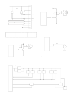
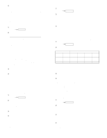
4 End of testing When the test ends normally When an error occurs 104 E- ~ - 104 Note: Calculation of key sumcheck data The hard code (hexadecimal number) at the position (excluding feed key) where there is an input data contact is added. However, the end key (CA/AT/NS) is not added. This data to which hard codes have been added is converted into a decimal number value, which will become the sumcheck data that will be entered when the Diag is started. 5) MODE SWITCH TEST 1 Key operation 105 RCPT/PO 2 Test procedure Display 1 0 5 X MODE: _PGM_VOID_OFF_OP X/Z_REG_MGR_X1/Z1_X2/Z2____PGM x: 1 2 9 3 4 5 6 7 1 The above x must be read in the correct order. (If the contact is open, 9 will be displayed.) 3 Check: The display during testing and the content of the completion print. 4 End of testing When the test ends normally: 105 When an error occurs: E- ~ - 105 6) PRINTER SENSOR TEST 1 Key operation 106 RCPT/PO 2 Test procedure Check the status of paper end sensor and head up sensor. 7-segment display: 1 0 6 XY 3 Check the following: X:1 - Paper present O - Out of paper Y:1 - Head DOWN O - Head UP 4 End of testing You can exit the test mode by pressing any key and the printer prints the following: 106 7) CLOCK TEST 1 Key operation 107 RCPT/PO 2 Test procedure Displayed digit: 8 76 54 32 1 7-segment display: hour min sec Blinks at an interval of 0.5 sec. 3 Check that: "-" blinks and the clock counts up. 4 End of testing When any key is pressed, the date and time are printed and the test mode will terminated. Display 1 0 6 XXXXXX - XXXXXX year month day hour min sec 8) DRAWER 1 OPEN AND SENSOR TEST 1 Key operation 110 RCPT/PO 2 Test procedure Display 1 1 0 X X: O = DRAWER OPEN C = DRAWER CLOSED 3 Check that: A) The drawer opens normally. B) The sensor correctly indicates the status of the drawer 1. *On the XE-A202, "C" (CLOSED) is always displayed. 4 End of testing You can exit the test mode by pressing any key. The printer prints the following. 110 9) EXTERNAL RAM TEST 1 Key operation 120 RCPT/PO 2 Test procedure The standard 128 Kbyte RAM is checked. The contents of the memory are lost after this test. RAM(08000H ~ 27FFFH area) is tested in the following procedure: a) Data in the test area is stored. b) Write "00H" c) Read and compare "00H" and then write"55H" d) Read and compare "55H" and then write"AAH" e) Read and compare "AAH" f) Restore stored data. If an error occurs at a step, the error is printed. If an error does not occur, the following addresses are checked. Addresses to be checked: 10000H , 10001H , 10002H , 10004H , 10008H 10010H , 10020H , 10040H , 10080H , 10100H , 10200H , 10400H , 10800H , 11000H , 12000H , 14000H , 18000H , 20000H Display 1 2 0 3 Check: A) The completion print. XE-A202U TEST FUNCTION - 13 -
-
 1
1 -
2
-
3
-
4
-
5
-
6
-
7
-
8
-
 9
9 -
 10
10 -
 11
11 -
 12
12 -
 13
13 -
 14
14 -
 15
15 -
 16
16 -
 17
17 -
 18
18 -
 19
19 -
20
-
21
-
22
-
23
-
24
-
25
-
26
-
27
 |
 |