Sharp XE-A202 Service Manual - Page 17
Caution To Be Used, When Connecting, The Rs-232 Cable - accessories
 |
UPC - 074000048270
View all Sharp XE-A202 manuals
Add to My Manuals
Save this manual to your list of manuals |
Page 17 highlights
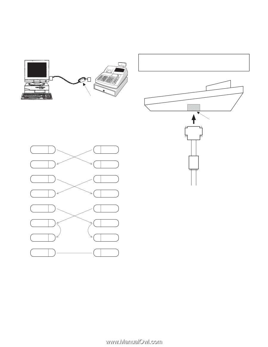
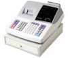
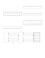
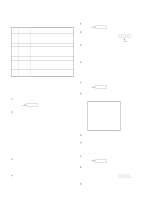
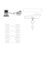
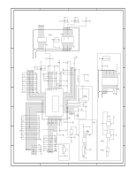
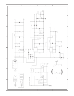
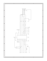
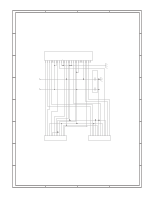
APPENDIX: RS232C CABLE The RS-232C cable (QCNWG3190BHZZ) provided together with the XE-A202 is used to connect the XE-A202 and a PC when using the customer support tool or performing IPL. When using the cable, connect the core side of the cable to the XEA202 as shown in the figure below. PC XE-A202 CHAPTER 7. CAUTION TO BE USED WHEN CONNECTING THE RS-232 CABLE When connecting the RS-232 cable to the XE-A202, be sure to observe the following condiiton: Use RS-232 cable (with core) of accessories. [This is a necessary to support the EMI (Electronics Magnetic Interface).] RS232C CABLE CORE The accessory RS-232C cable has the following internal connections: (Equivalent to a cross cable used in the conventional connection of ECR-ECR) 9PIN D-SUB SD 3 9PIN D-SUB 3 SD RD 2 2 RD RTS 7 DCD 1 7 RTS 1 DCD DTR 4 4 DTR DSR 6 6 DSR CTS 8 8 CTS SG 5 5 SG SD : TRANSMITTED DATA RD : RECEIVED DATA DTR : DATA TERMINAL READY DSR : DATA SET READY RTS : REQUEST TO SEND DCD : DATA CARRIER DETECTOR CTS : CLEAR TO SEND RS-232 CONNECTOR Use RS-232 cable (with core) of accessories. XE-A202U CAUTION TO BE USED WHEN CONNECTING THE RS-232 CABLE - 16 -
-
 1
1 -
2
-
3
-
4
-
5
-
6
-
7
-
8
-
9
-
10
-
11
-
 12
12 -
 13
13 -
 14
14 -
 15
15 -
 16
16 -
 17
17 -
 18
18 -
 19
19 -
 20
20 -
 21
21 -
 22
22 -
23
-
24
-
25
-
26
-
27
 |
 |