Sharp XE-A202 Service Manual - Page 11
Paper Take Up Motor Drive Circuit, Drawer Drive Circuit, Buzzer Drive Circuit, Keyboard Circuit
 |
UPC - 074000048270
View all Sharp XE-A202 manuals
Add to My Manuals
Save this manual to your list of manuals |
Page 11 highlights
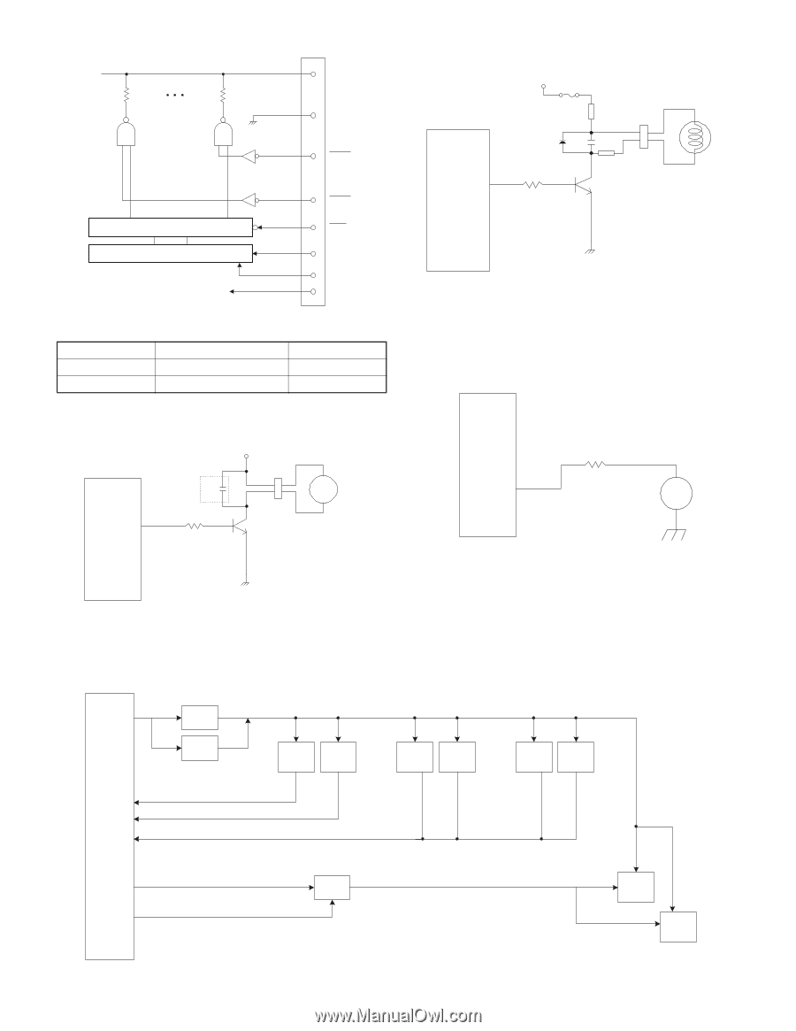
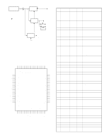
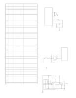
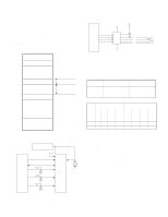
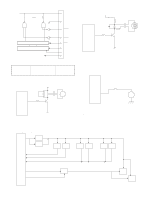
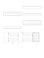
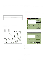
Thermal head block daigram Dot #288 Dot #1 5,6,18,19 9,10,14,15 11 VP GND STB1 Latch register Shift register Thermal head strobe terminals STB No. 1 2 Dot No. 1 ~ 144 145 ~ 288 13 STB2 7 LAT 16 CLK 17 DAT 12 VCC Connector Number of dots 144 144 9. DRAWER DRIVE CIRCUIT V0 F6 T400mA/250V FB2 CPU DIA IN4002 DR1 R102 /RTS0 (38pin) 1K C80 0.1u FB3 CN6 Q9 2SD2212 DRAWER FB2, FB3: Jumper Wire When the DR1 signal from the CPU is HIGH, Q9 is turned on to operate the solenoid. 10. BUZZER DRIVE CIRCUIT 8. PAPER TAKE UP MOTOR DRIVE CIRCUIT VH C79 CPU MOTOR TA4IN/U (21pin) R101 1K CN5 Q13 2SD2212 M MOTOR When the MOTOR signal from the CPU is HIGH, Q1 is turned on to operate the motor. CPU TA4OUT/U 22pin 470 R86 BZ BZ When the pulse signal (about 4KHz) is generated from the CPU, the buzzer sounds. 11. KEYBOARD CIRCUIT P10-13 P10-13 /S0-7 HC138 P10-13 /S8-9 HC138 /S0-9 /S0-7 Key Matrix Mode Switch P90 CPU P91 P92-97 P92-97 P91 D0-7 /CS3 D0-7 /CS3 74HC374 /S0-9 /S1 /S3 Paper Head up feed key sensor /S4 /S9 Paper end sensor RS232 /CI signal /S0 - 9 a,b,c,d,e,f,g,dp G1',G2', G3'G4',G5', G6',G7 Front display A',B',C',D',E',F',G',DP' Pop-up display Four P10-13 signals from the CPU are converted into 16 strobe signals by two 74HC138 for use in various functions. XE-A202U HARDWARE DESCRIPTION - 10 -
-
 1
1 -
2
-
3
-
4
-
5
-
 6
6 -
 7
7 -
 8
8 -
 9
9 -
 10
10 -
 11
11 -
 12
12 -
 13
13 -
 14
14 -
 15
15 -
 16
16 -
17
-
18
-
19
-
20
-
21
-
22
-
23
-
24
-
25
-
26
-
27
 |
 |