Sharp XV-Z9000U XVZ9000U Operation Manual - Page 10
Side and Rear View - manual
 |
UPC - 074000358126
View all Sharp XV-Z9000U manuals
Add to My Manuals
Save this manual to your list of manuals |
Page 10 highlights
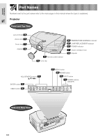
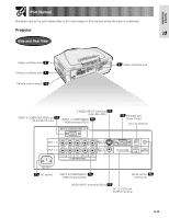
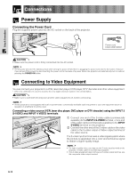
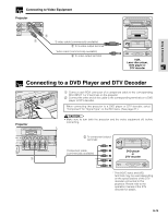
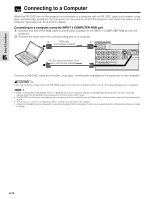
Important Information Part Names Numbers next to the part names refer to the main pages in this manual where the topic is explained. Projector Side and Rear View Intake ventilative hole 4 Exhaust ventilative hole 4 Remote control sensor 16 4 Intake ventilative hole INPUT 5 COMPUTER-RGB port 15 (15-pin Mini D-sub) S-VIDEO INPUT 3 terminal 13 (4-pin Mini DIN) INPUT 1 COMPONENT/ 14 RGB terminals (RCA) 15 RS-232C port (9-pin D-sub) DC 12V OUTPUT 13 AC socket INPUT 2 COMPONENT/ 14 RGB terminals (RCA) Wired remote 16 control jack VIDEO INPUT 4 terminal (RCA) 13 DC 12 V 200 mA OUTPUT terminal E-10
-
 1
1 -
2
-
3
-
4
-
 5
5 -
 6
6 -
 7
7 -
 8
8 -
 9
9 -
 10
10 -
 11
11 -
 12
12 -
 13
13 -
 14
14 -
 15
15 -
16
-
17
-
18
-
19
-
20
-
21
-
22
-
23
-
24
-
25
-
26
-
27
-
28
-
29
-
30
-
31
-
32
-
33
-
34
-
35
-
36
-
37
-
38
-
39
-
40
-
41
-
42
-
43
-
44
-
45
-
46
-
47
-
48
-
49
-
50
-
51
-
52
-
53
-
54
-
55
-
56
-
57
-
58
-
59
-
60
-
61
 |
 |

E-10
Important
Information
Part Names
Projector
Numbers next to the part names refer to the main pages in this manual where the topic is explained.
Side and Rear View
14
13
14
15
4
4
13
Intake ventilative hole
Exhaust ventilative hole
16
Remote control sensor
16
AC socket
DC 12 V 200 mA
OUTPUT terminal
Intake ventilative hole
4
15
INPUT 5 COMPUTER-RGB port
(15-pin Mini D-sub)
INPUT 1 COMPONENT/
RGB terminals (RCA)
INPUT 2 COMPONENT/
RGB terminals (RCA)
Wired remote
control jack
VIDEO INPUT 4 terminal (RCA)
13
S-VIDEO INPUT 3 terminal
(4-pin Mini DIN)
DC 12V OUTPUT
RS-232C port
(9-pin D-sub)