Sharp XV-Z9000U XVZ9000U Operation Manual - Page 51
Connecting Pin Assignments
 |
UPC - 074000358126
View all Sharp XV-Z9000U manuals
Add to My Manuals
Save this manual to your list of manuals |
Page 51 highlights
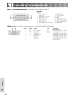
Connecting Pin Assignments INPUT 5 RGB Signal Input Port: 15-pin Mini D-sub female connector RGB Input Analog 1. Video input (red) 2. Video input 11 15 (green/sync on green) 6 10 3. Video input (blue) 1 5 4. Not connected 5. Composite sync 6. Earth (red) 7. Earth (green/sync on green) 8. Earth (blue) 9. Not connected 10. GND 11. GND 12. Bi-directional data 13. Horizontal sync signal 14. Vertical sync signal 15. Data clock RS-232C Port: 9-pin D-sub male connector of the DIN-D-sub RS-232C cable 96 5 1 Pin No. 1 2 3 4 5 6 7 8 9 Signal RD SD SG Name Receive Data Send Data Reserved Signal Ground Reserved Reserved Reserved I/O Input Output Reference Not connected Connected to internal circuit Connected to internal circuit Connected to internal circuit Connected to internal circuit Connected to internal circuit Connected to internal circuit Connected to internal circuit Not connected Appendix E-51
-
 1
1 -
2
-
3
-
4
-
5
-
6
-
7
-
8
-
9
-
10
-
11
-
12
-
13
-
14
-
15
-
16
-
17
-
18
-
19
-
20
-
21
-
22
-
23
-
24
-
25
-
26
-
27
-
28
-
29
-
30
-
31
-
32
-
33
-
34
-
35
-
36
-
37
-
38
-
39
-
40
-
41
-
42
-
43
-
44
-
45
-
 46
46 -
 47
47 -
 48
48 -
 49
49 -
 50
50 -
 51
51 -
 52
52 -
 53
53 -
 54
54 -
 55
55 -
 56
56 -
57
-
58
-
59
-
60
-
61
 |
 |
