Sony 757MX Service Manual - Page 16
Gear Lomini/load 1, Operation, Check
 |
UPC - 027242597846
View all Sony 757MX manuals
Add to My Manuals
Save this manual to your list of manuals |
Page 16 highlights
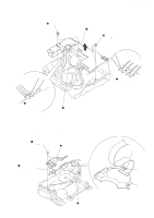
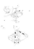
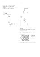
CDX-757MX 3-3. GEAR (LOMINI)/(LOAD 1) ASSY gear (LOAD 2) gear (LOMINI) chuck plate 2 Attach the gear (LOMINI) at the position shown in Fig. A. shaft (rotary prevention C) B 1 Move the lever (LOCK 3A) fully in the direction of arrow B to move the chuck plate up. marking Fig. A slit 3 Attach the gear (LOAD 1) assy with its facing inside. 4 stop ring 1.5 (E type) 3-4. OPERATION CHECK 1 Confirm that the slider moves in the direction of arrow C to move down the chuck plate if the gear (LOAD 1) is rotated in the direction of arrow A or the chuck plate moves up and the slider moves in the direction of arrow D if the gear is rotated in the direction of arrow B. chuck plate slider D C A B gear (LOAD 1) assy 16
-
 1
1 -
2
-
3
-
4
-
5
-
6
-
7
-
8
-
9
-
10
-
 11
11 -
 12
12 -
 13
13 -
 14
14 -
 15
15 -
 16
16 -
 17
17 -
 18
18 -
 19
19 -
 20
20 -
 21
21 -
22
-
23
-
24
-
25
-
26
-
27
-
28
-
29
-
30
-
31
-
32
-
33
-
34
-
35
-
36
-
37
-
38
-
39
-
40
-
41
-
42
-
43
-
44
-
45
-
46
-
47
-
48
-
49
-
50
-
51
-
52
-
53
-
54
-
55
-
56
-
57
-
58
-
59
-
60
-
61
-
62
-
63
 |
 |

CDX-757MX
16
3-3.
GEAR (LOMINI)/(LOAD 1)
ASSY
3-4.
OPERATION
CHECK
1
Confirm that the slider moves in the direction of arrow
C
to move down
the chuck plate if the gear (LOAD 1) is rotated in the direction of arrow
A
or the chuck plate moves up and the slider moves in the direction of
arrow
D
if the gear is rotated in the direction of arrow
B
.
gear (LOAD 2)
gear (LOMINI)
marking
Fig. A
chuck plate
2
Attach the gear (LOMINI) at the position
shown in Fig. A.
shaft (rotary prevention C)
1
Move the lever (LOCK 3A)
fully in the direction of arrow
B
to move the chuck plate up.
B
4
stop ring 1.5 (E type)
3
Attach the gear (LOAD 1) assy
with its facing inside.
slit
chuck plate
slider
gear (LOAD 1) assy
A
B
C
D