Sony 757MX Service Manual - Page 17
Cdx-757mx, Mechanical, Adjustment - cdx cable
 |
UPC - 027242597846
View all Sony 757MX manuals
Add to My Manuals
Save this manual to your list of manuals |
Page 17 highlights
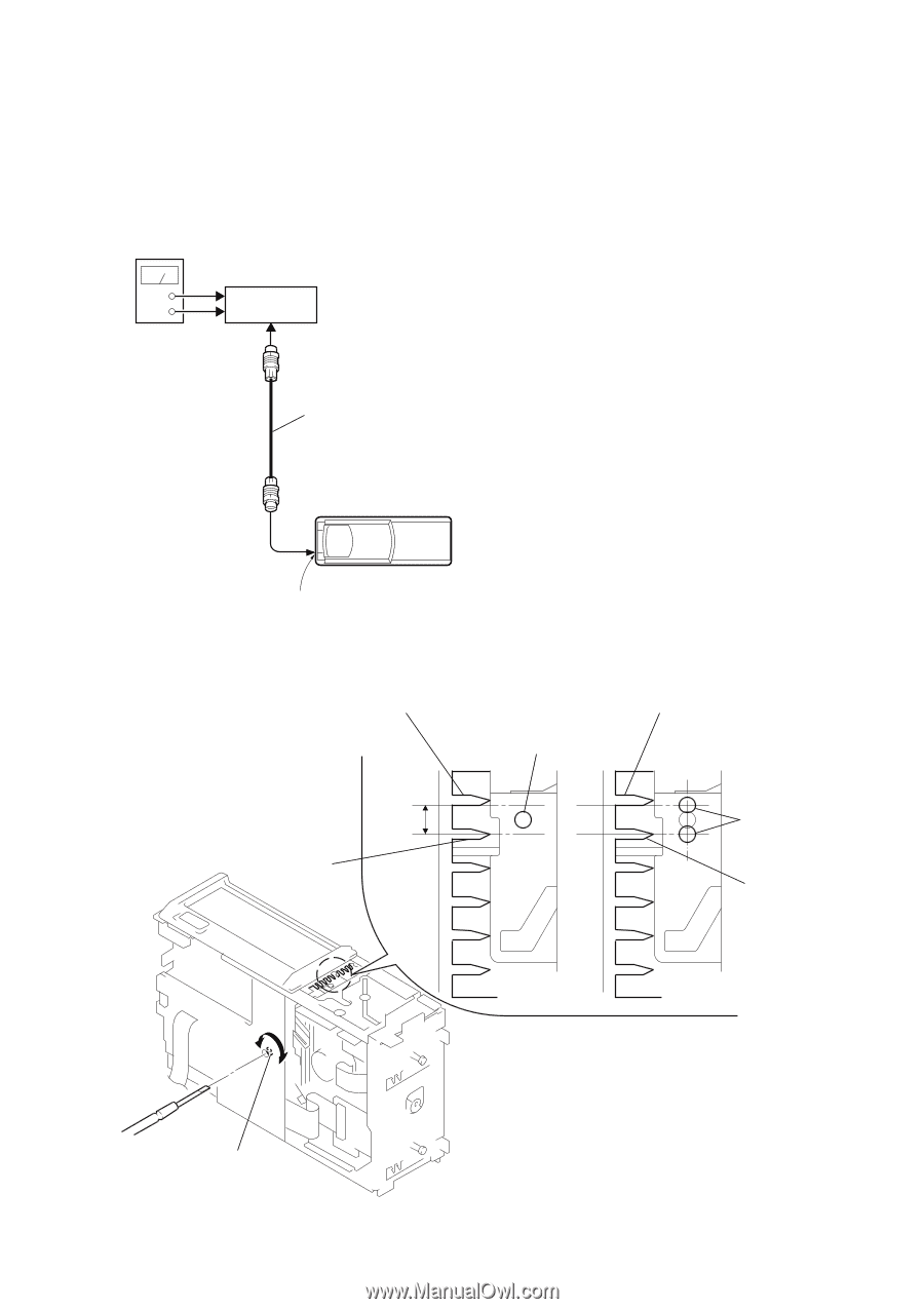
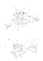
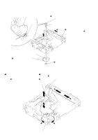
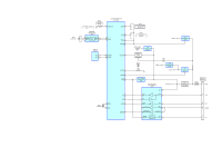
SECTION 4 MECHANICAL ADJUSTMENT CDX-757MX • Elevator Height (Address) Adjustment Note: This adjustments is necessary when the system controller (IC201), variable resistor (RV201), slider (R), slider (L), or chassis (ELV) was replaced for any repair. Connection: power supply (DC 14.4 V) + GND master unit BUS cable Adjustment Method: 1. Connect this set to the master unit (e.g. MDX-C7970), load a disc magazine, and place the set vertically as shown below. 2. Connect the regulated power supply to the master unit, and turn the power on. 3. Press the DISC button on the master unit and select DISC 5. 4. At this time, if the elevator shaft does not position between comb teeth A and B at addresses 5 and 6 as shown below, adjust the following. 5. Press repeatedly the DISC + and - buttons on the master unit so that the elevator shafts moves from address 6 to address 5, or from 5 to 6. At this time, adjust RV201 on the main board so that the elevator shaft positions smoothly between comb teeth A and B. 6. Further, place the set horizontally and make same adjustment as mentioned above. 7. After adjustment at addresses 5 to 6 is finished, check all operations from addresses 1 to 10 with the set placed vertically and horizontally respectively to confirm that the elevator shaft positions in a range between comb teeth A to B. compact disc changer CONTROL connector (CN901) comb tooth at address 6 A B comb tooth at address 5 comb tooth at address 6 elevator shaft A elevator shaft B comb tooth at address 5 OK NG RV201 17
-
 1
1 -
2
-
3
-
4
-
5
-
6
-
7
-
8
-
9
-
10
-
11
-
 12
12 -
 13
13 -
 14
14 -
 15
15 -
 16
16 -
 17
17 -
 18
18 -
 19
19 -
 20
20 -
 21
21 -
 22
22 -
23
-
24
-
25
-
26
-
27
-
28
-
29
-
30
-
31
-
32
-
33
-
34
-
35
-
36
-
37
-
38
-
39
-
40
-
41
-
42
-
43
-
44
-
45
-
46
-
47
-
48
-
49
-
50
-
51
-
52
-
53
-
54
-
55
-
56
-
57
-
58
-
59
-
60
-
61
-
62
-
63
 |
 |