Sony 757MX Service Manual - Page 5

Table, Contents, Servicing Notes, General, Disassembly, Assembly, Mechanical, Adjustment, Electrical - cdx rf

Page 5 highlights

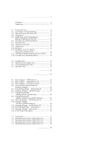
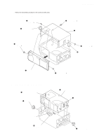
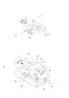
TABLE OF CONTENTS SERVICING NOTES 2 1. GENERAL Installation 6 Connections 7 2. DISASSEMBLY 2-1. Disassembly Flow 8 2-2. Case (Upper. T), Front Panel Assy 9 2-3. Mechanism Deck (MG-251B-137 9 2-4. JACK Board 10 2-5. MAIN Board, Slide Variable Resistor (Elevator Height Sensor) (RV202 10 2-6. ELJ Motor Assy (Elevator) (M104 11 2-7. Escutcheon (T 11 2-8. Chassis (U.S) Sub Assy 12 2-9. Chassis Assy 12 2-10. RF Board 13 2-11. Sled Motor Assy (251) (M101), Optical Pick-up (KSS-720A 13 2-12. LSW Board, Spindle Motor (S) Sub Assy (M102) ........ 14 2-13. ELJ Motor Assy (Chucking) (M103 14 3. ASSEMBLY 3-1. Assembly Flow 15 3-2. Optical Pick-up Complete Assy 15 3-3. Gear (Lomini)/(Load 1) Assy 16 3-4. Operation Check 16 4. MECHANICAL ADJUSTMENT 17 5. ELECTRICAL CHECK 18 6. DIAGRAMS 6-1. Block Diagram - SERVO Section 20 6-2. Block Diagram - MAIN Section (1/2 21 6-3. Block Diagram - MAIN Section (2/2 22 6-4. Note for Printed Wiring Boards and Schematic Diagrams 23 6-5. Printed Wiring Boards - RF/LSW Boards 24 6-6. Schematic Diagram - RF/LSW Boards 25 6-7. Printed Wiring Boards - MAIN Board (Component Side 26 6-8. Printed Wiring Boards - MAIN (Conductor Side)/SWITCH Boards 27 6-9. Schematic Diagram - MAIN Board (1/3 28 6-10. Schematic Diagram - MAIN (2/3)/SWITCH Boards 29 6-11. Schematic Diagram - MAIN Board (3/3 30 6-12. Printed Wiring Boards - JACK Board 32 6-13. Schematic Diagram - JACK Board 33 6-14. IC Pin Function Description 39 7. EXPLODED VIEWS 7-1. Case Section 41 7-2. Mechanism Deck Section-1 (MG-251B-137 42 7-3. Mechanism Deck Section-2 (MG-251B-137 43 7-4. Mechanism Deck Section-3 (MG-251B-137 44 7-5. Mechanism Deck Section-4 (MG-251B-137 45 8. ELECTRICAL PARTS LIST 46 CDX-757MX 5

  • 1
  • 2
  • 3
  • 4
  • 5
  • 6
  • 7
  • 8
  • 9
  • 10
  • 11
  • 12
  • 13
  • 14
  • 15
  • 16
  • 17
  • 18
  • 19
  • 20
  • 21
  • 22
  • 23
  • 24
  • 25
  • 26
  • 27
  • 28
  • 29
  • 30
  • 31
  • 32
  • 33
  • 34
  • 35
  • 36
  • 37
  • 38
  • 39
  • 40
  • 41
  • 42
  • 43
  • 44
  • 45
  • 46
  • 47
  • 48
  • 49
  • 50
  • 51
  • 52
  • 53
  • 54
  • 55
  • 56
  • 57
  • 58
  • 59
  • 60
  • 61
  • 62
  • 63

5
CDX-757MX
TABLE
OF
CONTENTS
SERVICING NOTES
..........................................................
2
1.
GENERAL
Installation
.......................................................................
6
Connections
.....................................................................
7
2.
DISASSEMBLY
2-1.
Disassembly Flow
...........................................................
8
2-2.
Case (Upper. T), Front Panel Assy
.................................
9
2-3.
Mechanism Deck (MG-251B-137)
.................................
9
2-4.
JACK Board
....................................................................
10
2-5.
MAIN Board, Slide Variable Resistor
(Elevator Height Sensor) (RV202)
.................................
10
2-6.
ELJ Motor Assy (Elevator) (M104)
................................
11
2-7.
Escutcheon (T)
................................................................
11
2-8.
Chassis (U.S) Sub Assy
..................................................
12
2-9.
Chassis Assy
....................................................................
12
2-10.
RF Board
.........................................................................
13
2-11.
Sled Motor Assy (251) (M101),
Optical Pick-up (KSS-720A)
..........................................
13
2-12.
LSW Board, Spindle Motor (S) Sub Assy (M102)
........
14
2-13.
ELJ Motor Assy (Chucking) (M103)
.............................
14
3.
ASSEMBLY
3-1.
Assembly Flow
................................................................
15
3-2.
Optical Pick-up Complete Assy
......................................
15
3-3.
Gear (Lomini)/(Load 1) Assy
.........................................
16
3-4.
Operation Check
.............................................................
16
4.
MECHANICAL
ADJUSTMENT
..........................
17
5.
ELECTRICAL
CHECK
..........................................
18
6.
DIAGRAMS
6-1.
Block Diagram
– SERVO Section –
..............................
20
6-2.
Block Diagram
– MAIN Section (1/2) –
.......................
21
6-3.
Block Diagram
– MAIN Section (2/2) –
.......................
22
6-4.
Note for Printed Wiring Boards and
Schematic Diagrams
.......................................................
23
6-5.
Printed Wiring Boards – RF/LSW Boards –
.................
24
6-6.
Schematic Diagram
– RF/LSW Boards –
......................
25
6-7.
Printed Wiring Boards
– MAIN Board (Component Side) –
..............................
26
6-8.
Printed Wiring Boards
– MAIN (Conductor Side)/SWITCH Boards –
..............
27
6-9.
Schematic Diagram
– MAIN Board (1/3) –
..................
28
6-10.
Schematic Diagram
– MAIN (2/3)/SWITCH Boards –
..................................
29
6-11.
Schematic Diagram
– MAIN Board (3/3) –
..................
30
6-12.
Printed Wiring Boards
– JACK Board –
........................
32
6-13.
Schematic Diagram – JACK Board –
.............................
33
6-14.
IC Pin Function Description
...........................................
39
7.
EXPLODED
VIEWS
7-1.
Case Section
....................................................................
41
7-2.
Mechanism Deck Section-1 (MG-251B-137)
................
42
7-3.
Mechanism Deck Section-2 (MG-251B-137)
................
43
7-4.
Mechanism Deck Section-3 (MG-251B-137)
................
44
7-5.
Mechanism Deck Section-4 (MG-251B-137)
................
45
8.
ELECTRICAL
PARTS
LIST
...............................
46