Sony 757MX Service Manual - Page 18
Cdx-757mx, Electrical, Check - cdx power cable
 |
UPC - 027242597846
View all Sony 757MX manuals
Add to My Manuals
Save this manual to your list of manuals |
Page 18 highlights
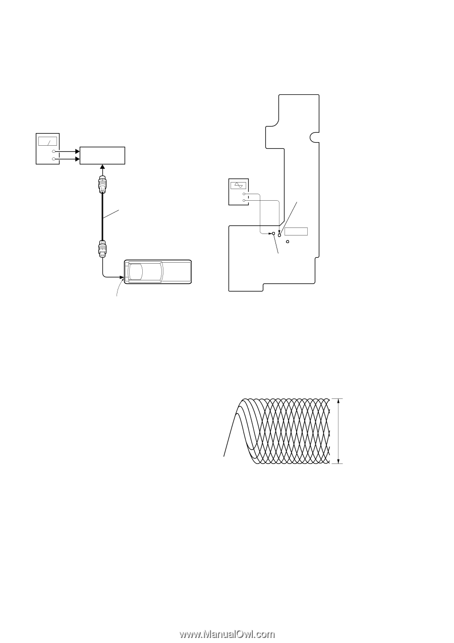
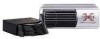
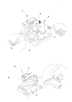
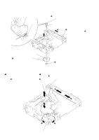
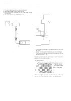
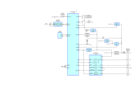
CDX-757MX SECTION 5 ELECTRICAL CHECK Note: 1. This check is performed with the set placed horizontally. 2. Power supply voltage: DC14.4 V (more than 3 A). 3. Be sure to use the disc "YEDS-18" parts code: 3-702-101-01, but only when indicated. 4. Use a master unit that supports SONY bus system. FOCUS BIAS CHECK Connection: - RF Board (Component Side) - Connection: power supply (DC 14.4 V) + GND master unit oscilloscope (AC range) BUS cable + - TP (VC) IC101 TP (RFAC) compact disc changer CONTROL connector (CN901) Procedure: 1. Connect the oscilloscope to TP (RFAC) and TP (VC) on the RF board. 2. Put the set into play mode by loading the disc (YEDS-18). 3. Confirm that oscilloscope waveform is clear and check RF sig- nal level is correct or not. Note: Clear RF signal waveform means that the shape "◊" can be clearly distinguished at the center of the waveform. RF signal waveform VOLT/DIV: 200 mV TIME/DIV: 500 ns (10 : 1 probe in use) level: 1.4 ± 0.3 Vp-p When observing the eye pattern, set the oscilloscope to AC range and raise the vertical sensitivity so that it may be easily seen. 18
-
 1
1 -
2
-
3
-
4
-
5
-
6
-
7
-
8
-
9
-
10
-
11
-
12
-
 13
13 -
 14
14 -
 15
15 -
 16
16 -
 17
17 -
 18
18 -
 19
19 -
 20
20 -
 21
21 -
 22
22 -
 23
23 -
24
-
25
-
26
-
27
-
28
-
29
-
30
-
31
-
32
-
33
-
34
-
35
-
36
-
37
-
38
-
39
-
40
-
41
-
42
-
43
-
44
-
45
-
46
-
47
-
48
-
49
-
50
-
51
-
52
-
53
-
54
-
55
-
56
-
57
-
58
-
59
-
60
-
61
-
62
-
63
 |
 |