Sony 757MX Service Manual - Page 2
Cdx-757mx, Servicing, Notes - cdx manual
 |
UPC - 027242597846
View all Sony 757MX manuals
Add to My Manuals
Save this manual to your list of manuals |
Page 2 highlights
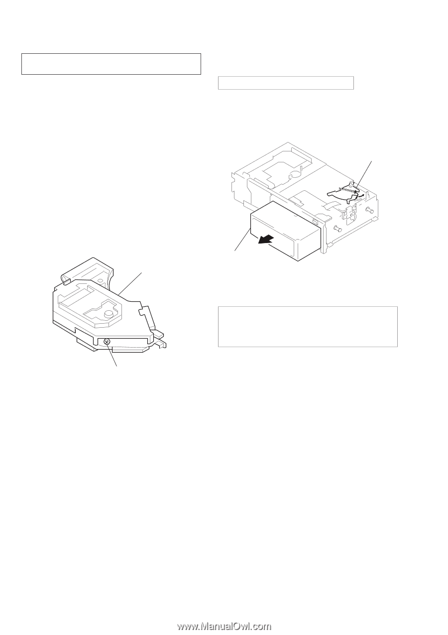
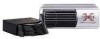
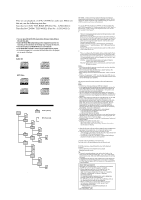
CDX-757MX SERVICING NOTES NOTES ON HANDLING THE OPTICAL PICKUP BLOCK OR BASE UNIT The laser diode in the optical pick-up block may suffer electrostatic breakdown because of the potential difference generated by the charged electrostatic load, etc. on clothing and the human body. During repair, pay attention to electrostatic breakdown and also use the procedure in the printed matter which is included in the repair parts. The flexible board is easily damaged and should be handled with care. NOTES ON LASER DIODE EMISSION CHECK The laser beam on this model is concentrated so as to be focused on the disc reflective surface by the objective lens in the optical pick-up block. Therefore, when checking the laser diode emission, observe from more than 30 cm away from the objective lens. US/Canadian model: If the optical pick-up block is defective, please replace the whole optical pick-up block. Never turn the semi-fixed resistor located at the side of optical pick-up block. DISC MAGAZINE GETTING OUT PROCEDURE ON THE POWER SUPPLY IS OFF Remove the CASE (LOWER. T) beforehand 1) Press the lever (ML.S) assy in the direction of arrow A. 2) Removal the magazine assy. Note: Take out the magazine only when the tray is completely within the magazine. If the disk or tray is sticking out, turn on the power and eject the magazine. Lever (ML.S) A Magazine assy OPTICAL PICK-UP BLOCK SEMI-FIXED RESISTOR CAUTION Use of controls or adjustments or performance of procedures other than those specified herein may result in hazardous radiation exposure. Flexible Circuit Board Repairing • Keep the temperature of the soldering iron around 270 ˚C dur- ing repairing. • Do not touch the soldering iron on the same conductor of the circuit board (within 3 times). • Be careful not to apply force on the conductor when soldering or unsoldering. Notes on chip component replacement • Never reuse a disconnected chip component. • Notice that the minus side of a tantalum capacitor may be dam- aged by heat. SAFETY-RELATED COMPONENT WARNING!! COMPONENTS IDENTIFIED BY MARK 0 OR DOTTED LINE WITH MARK 0 ON THE SCHEMATIC DIAGRAMS AND IN THE PARTS LIST ARE CRITICAL TO SAFE OPERATION. REPLACE THESE COMPONENTS WITH SONY PARTS WHOSE PART NUMBERS APPEAR AS SHOWN IN THIS MANUAL OR IN SUPPLEMENTS PUBLISHED BY SONY. ATTENTION AU COMPOSANT AYANT RAPPORT À LA SÉCURITÉ! LES COMPOSANTS IDENTIFIÉS PAR UNE MARQUE 0 SUR LES DIAGRAMMES SCHÉMATIQUES ET LA LISTE DES PIÈCES SONT CRITIQUES POUR LA SÉCURITÉ DE FONCTIONNEMENT. NE REMPLACER CES COMPOSANTS QUE PAR DES PIÈCES SONY DONT LES NUMÉROS SONT DONNÉS DANS CE MANUEL OU DANS LES SUPPLÉMENTS PUBLIÉS PAR SONY. 2
-
 1
1 -
 2
2 -
 3
3 -
 4
4 -
 5
5 -
 6
6 -
 7
7 -
 8
8 -
9
-
10
-
11
-
12
-
13
-
14
-
15
-
16
-
17
-
18
-
19
-
20
-
21
-
22
-
23
-
24
-
25
-
26
-
27
-
28
-
29
-
30
-
31
-
32
-
33
-
34
-
35
-
36
-
37
-
38
-
39
-
40
-
41
-
42
-
43
-
44
-
45
-
46
-
47
-
48
-
49
-
50
-
51
-
52
-
53
-
54
-
55
-
56
-
57
-
58
-
59
-
60
-
61
-
62
-
63
 |
 |