Sony 757MX Service Manual - Page 39
Function, Description
 |
UPC - 027242597846
View all Sony 757MX manuals
Add to My Manuals
Save this manual to your list of manuals |
Page 39 highlights
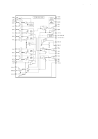
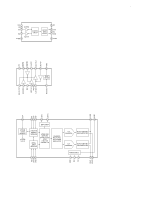
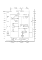
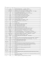
CDX-757MX 6-14. IC PIN FUNCTION DESCRIPTION • MAIN BOARD IC201 HD6432238RWN21TEIV (SYSTEM CONTROLLER) Pin No. Pin Name I/O Description 1 2 3 4 5 6 7 8 9 10 11 12 13 14 15 16 17 18 19 20 21 22 23 24 25 26 27, 28 29 30 31 32 33 to 35 36 37 38 39 40 41 42 43 to 49 50 51 TEST DECXRST DECSTBY FOK GFS SCLK SENS CDCLK CDLAT CDDAT XRST CVCC NC VSS XQOK XRDE XWRE DAC-DATA DAC-CLK DAC-LAT ESPSEL TEXTSEL CFSEL DOUT SEL MAG-SW MUTE NC CDON EVON PCTX PCRX NC ELVF ELVR SCOR NC GRSCOR NC AVSS NCI EHS NCI I Test mode setting terminal "L": test mode Not used O Reset signal output to the CD-ROM/MP3 decoder "L": reset O Standby mode control signal output to the CD-ROM/MP3 decoder "H": standby I Focus OK signal input from the DSP "L": NG, "H": OK I Guard frame sync signal input from the DSP "L": NG, "H": OK O Serial data reading clock signal output to the DSP I Internal status signal (sense signal) input from the DSP O Serial data transfer clock signal output to the DSP O Serial data latch pulse signal output to the DSP O Serial data output to the DSP O System reset signal output to the DSP "L": reset - Power supply terminal (+3.3V) (for system) O Not used - Ground terminal O Subcode Q OK pulse signal output to the DSP O Read enable signal output to the DSP O Write enable signal output to the DSP O Mode control data output to the D/A converter O Mode control data transfer clock signal output to the D/A converter O Mode control data latch pulse signal output to the D/A converter I ESP mode setting terminal "L": ESP on (fixed at "L" in this set) I CD text mode setting terminal "L": CD text on (fixed at "L" in this set) I Custom file on/off setting terminal "L": custom file on (fixed at "L" in this set) I Input terminal for digital out on/off setting "L": digital out on Not used I Magazine detect switch input terminal Not used O Audio line muting on/off control signal output "H": muting on O Not used O D/A convert and servo sections power supply on/off control signal output "H": power on O Mechanism deck section power supply on/off control signal output "H": power on O PC connecting output terminal for UART I PC connecting input terminal for UART O Not used O Motor drive signal (elevator up direction) output to the elevator motor drive O Motor drive signal (elevator down direction) output to the elevator motor drive I Subcode sync (S0+S1) detection signal input from the DSP O Not used I Subcode sync (S0+S1) detection signal input from the DSP O Not used - Ground terminal (for A/D converter) I Not used I Elevator height position detection signal input from the elevator height sensor (A/D input) I Not used 52 MCK I Input of detection signal for the fine adjustment (elevator height (address) adjustment) of elevator height position (A/D input) 53 VREF I Reference voltage (+3.3V) input terminal (for A/D converter) 39
-
 1
1 -
2
-
3
-
4
-
5
-
6
-
7
-
8
-
9
-
10
-
11
-
12
-
13
-
14
-
15
-
16
-
17
-
18
-
19
-
20
-
21
-
22
-
23
-
24
-
25
-
26
-
27
-
28
-
29
-
30
-
31
-
32
-
33
-
 34
34 -
 35
35 -
 36
36 -
 37
37 -
 38
38 -
 39
39 -
 40
40 -
 41
41 -
 42
42 -
 43
43 -
 44
44 -
45
-
46
-
47
-
48
-
49
-
50
-
51
-
52
-
53
-
54
-
55
-
56
-
57
-
58
-
59
-
60
-
61
-
62
-
63
 |
 |
