Sony DIR-TC1 Instruction Manual - Page 4
Hooking Up, Inserting the transmitter - dir tc 1
 |
View all Sony DIR-TC1 manuals
Add to My Manuals
Save this manual to your list of manuals |
Page 4 highlights
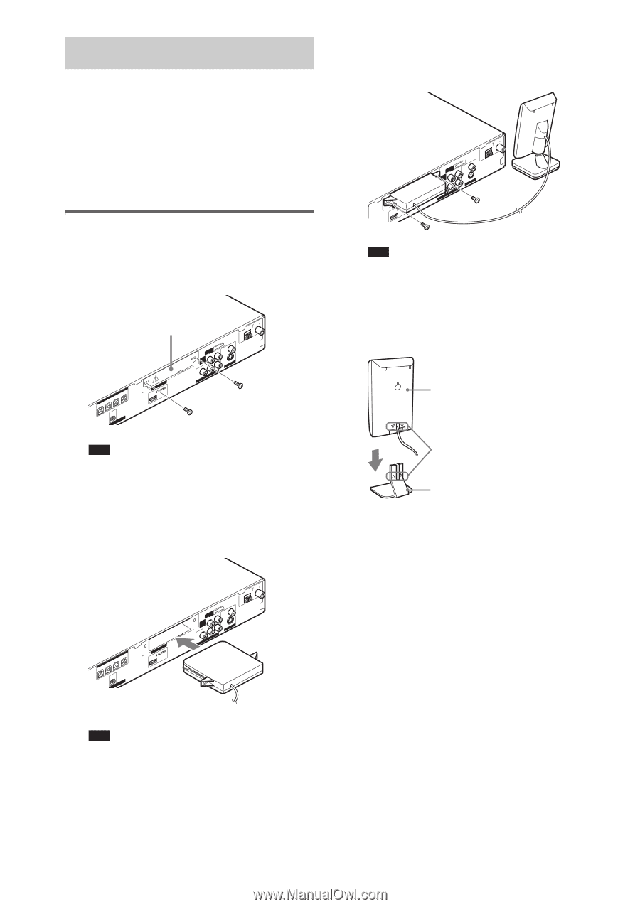
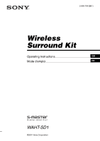
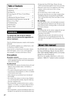
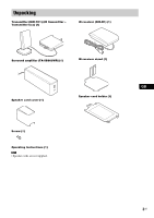
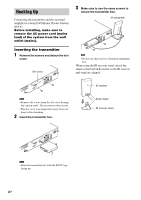
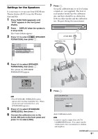
Hooking Up Connecting the transmitter and the surround amplifier to a Sony DVD Home Theatre System (DAV). Before installing, make sure to remove the AC power cord (mains lead) of the system from the wall outlet (mains). Inserting the transmitter 1 Remove the screws and detach the slot cover. FRONT R SPEAKESRUR R FRONT L SUR L D-LIGHT SYNC OUT Slot cover CFOMA7X5IAL AM DIR-TC1 (DVDOUOTNLY) DMPROARUTDIO IN L VITDVE/O (DVD ONLY) CYOMPONPBE/CNBT VIDEPOR/OCRUT VIDEO (DSVVDIDOMNELOOY)NITOR OUT Note • Remove the screws from the slot cover bearing the caution mark. Do not remove other screws. • The slot cover is no longer necessary; however, keep it after detaching. 2 Insert the transmitter box. 3 Make sure to use the same screws to secure the transmitter box. IR transmitter DIR-TC1 (DVDOUOTNLY) CFOMA7X5IAL AM DMPROARUTDIO IN L VITDVE/O (DVD ONLY) PB/CB CYOMPONENT VIDEPOR/OCRUT VIDEO (DSVVDIDOMNELOOY)NITOR OUT Note • Do not use other screws to fasten the transmitter box. When using the IR receiver stand, attach the stand so that both delta marks on the IR receiver and stand are aligned. IR receiver Delta marks IR receiver stand FRONT R SPEAKESRUR R FRONT L SUR L D-LIGHT SYNC OUT DIR-TC1 (DVDOUOTNLY) CFOMA7X5IAL AM DMPROARUTDIO IN L VITDVE/O (DVD ONLY) CYOMPONPBE/CNBT VIDEPOR/OCRUT VIDEO (DSVVDIDOMNELOOY)NITOR OUT Note • Insert the transmitter box with the SONY logo facing up. 4GB
-
 1
1 -
 2
2 -
 3
3 -
 4
4 -
 5
5 -
 6
6 -
 7
7 -
 8
8 -
 9
9 -
 10
10 -
11
-
12
-
13
-
14
-
15
-
16
-
17
-
18
-
19
-
20
-
21
-
22
-
23
-
24
-
25
-
26
-
27
-
28
-
29
-
30
-
31
-
32
 |
 |