Sony HCD-DH7BT Service Manual - Page 65
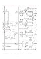
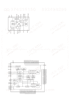
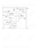
DMB15 BOARD, IC102, CXD9849R RF AMP, SERVO DSP, MPEG DECODER, Pin No., Pin Name, Description
 |
View all Sony HCD-DH7BT manuals
Add to My Manuals
Save this manual to your list of manuals |
Page 65 highlights
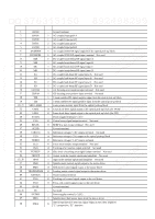
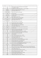
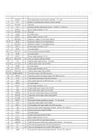
http://www.xiaoyu163.com HCD-DH3/DH5BT/DH7BT TEL 13942296513 QQ 376315150 892498299 TEL 13942296513 QQ 376315150 892498299 QQ 376315150 892498299 • ICPinFunctionDescription DMB15 BOARD IC102 CXD9849R (RF AMP, SERVO DSP, MPEG DECODER) Pin No. Pin Name I/O Description 1 AGND - Ground terminal 2 DVDA I AC coupled input path A 3 DVDB I AC coupled input path B 4 DVDC I AC coupled input path C 5 DVDD I AC coupled input path D 6 DVDRFIP I AC coupled DVD RF signal input from the optical pick-up block 7 DVDRFIN I AC coupled DVD RF signal input terminal Not used 8 MA I DC coupled main-beam RF signal input A 9 MB I DC coupled main-beam RF signal input B 10 MC I DC coupled main-beam RF signal input C 11 MD I DC coupled main-beam RF signal input D 12 SA I DC coupled sub-beam RF signal input A Not used 13 SB I DC coupled sub-beam RF signal input B Not used 14 SC I DC coupled sub-beam RF signal input C Not used 15 SD I DC coupled sub-beam RF signal input D Not used 16 CDFON I CD focusing error negative input terminal Not used 17 CDFOP I CD focusing error positive input terminal Not used 18 TNI I 3 beam satellite PD signal negative input from the optical pick-up block 19 TPI I 3 beam satellite PD signal positive input from the optical pick-up block TEL 13942296513 QQ 376315150 892498299 20, 21 22 MDI1, MDI2 LDO2 I Laser power monitor input from the optical pick-up block O Laser diode drive signal output to the optical pick-up block (for DVD) 23 LDO1 O Laser diode drive signal output to the optical pick-up block (for CD) 24 SVDD3 - Power supply terminal (+3.3V) 25 CSO O Central servo signal output terminal Not used 26 RFLVL O RFRP low pass output terminal Not used 27 SGND - Ground terminal 28 V2REFO O Reference voltage (+2.8V) output terminal Not used 29 V2O O Reference voltage (+2V) output to the optical pick-up block 30 VREFO O Reference voltage (+1.4V) output terminal 31 FEO O Focus error monitor output terminal Not used 32 TEO O Tracking error monitor output terminal Not used 33 TEZISLV O Slice level of tracking error signal output terminal Not used 34 OPOUT O Output from the internal operational amplifier Not used 35, 36 OPIN I Input to the internal operational amplifier Not used 37 DMO O Spindle motor control signal output to the motor driver 38 FMO O Sled motor control signal output to the motor driver 39 TROPENPWM O Loading motor control signal output to the motor driver 40 IOPMON I Power monitor terminal 41 TRO O Tracking coil control signal output to the coil driver 42 FOO O Focus coil control signal output to the coil driver 43 DVSS - Ground terminal www. xiaoyu163. com 44,45 46 47 NC DVDD3 SPFG - Not used - Power supply terminal (+3.3V) I Spindle motor hall sensor input from the motor driver 48 DSEL O Interlace/progressive selection signal output to the video amplifier "L": progressive, "H": interlace 65 http://www.xiaoyu163.com
-
 1
1 -
2
-
3
-
4
-
5
-
6
-
7
-
8
-
9
-
10
-
11
-
12
-
13
-
14
-
15
-
16
-
17
-
18
-
19
-
20
-
21
-
22
-
23
-
24
-
25
-
26
-
27
-
28
-
29
-
30
-
31
-
32
-
33
-
34
-
35
-
36
-
37
-
38
-
39
-
40
-
41
-
42
-
43
-
44
-
45
-
46
-
47
-
48
-
49
-
50
-
51
-
52
-
53
-
54
-
55
-
56
-
57
-
58
-
59
-
 60
60 -
 61
61 -
 62
62 -
 63
63 -
 64
64 -
 65
65 -
 66
66 -
 67
67 -
 68
68 -
 69
69 -
 70
70 -
71
-
72
-
73
-
74
-
75
-
76
-
77
-
78
-
79
-
80
-
81
-
82
-
83
-
84
-
85
-
86
-
87
-
88
-
89
-
90
-
91
-
92
-
93
-
94
-
95
-
96
-
97
-
98
-
99
-
100
-
101
-
102
-
103
-
104
-
105
-
106
-
107
-
108
-
109
-
110
-
111
-
112
-
113
-
114
-
115
-
116
-
117
-
118
-
119
-
120
-
121
-
122
-
123
-
124
-
125
-
126
-
127
-
128
-
129
-
130
 |
 |
