Sony KD-34XBR2 Primary User Manual - Page 16
DTV Controls and Connectors - no picture
 |
View all Sony KD-34XBR2 manuals
Add to My Manuals
Save this manual to your list of manuals |
Page 16 highlights
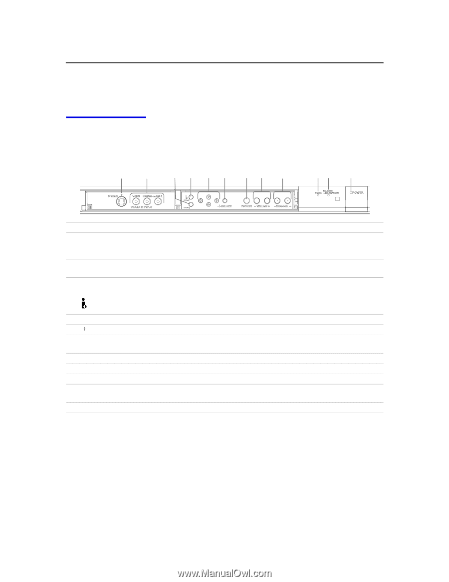
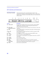
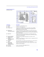
Connecting and Setting Up the DTV DTV Controls and Connectors Front Panel Controls The front panel provides convenient inputs for audio/video components you plan to connect temporarily, such as a camcorder or digital camera. It includes several buttons that you'll also find on the remote control. 1 2 3 4 5 6 78 9 q; qa qs Control 1 S VIDEO 2 INPUT 2 VIDEO 2 INPUT VIDEO/L(MONO)-AUDIO-R 3 MENU 4 i.LINK 5 B bVv 6 SELECT 7 TV/VIDEO 8 -VOLUME+ 9 -CHANNEL+ 0 TIMER qa STANDBY/ i.LINK STANDBY qs POWER Description Connects to the S VIDEO OUT jack of your camcorder or other S VIDEOequipped video component. Provides better picture quality than the VHF/UHF jacks or the Video IN jack. Connect to the audio and video OUT jacks on your camcorder or other video component. Press to display the DTV on-screen menu. Press again to exit from the menus. For details, see page 45. Press to display the i.LINK Control Panel. For details on using the i.LINK Control Panel, see page 42. Press B bVv to move the on-screen cursor and press SELECT to select. Press to select the on-screen highlighted item. Press repeatedly to step through the video equipment connected to your DTV's video inputs. Press to adjust the volume. Press to scan through channels. When lit, indicates one of the timers is set. For details, see pag e43. When lit in orange, indicates that i.LINK Standby is On. When lit in red, indicates that i.LINK Standby is Off. For details, see page 59. Press to turn on and off the DTV. 10
-
 1
1 -
2
-
3
-
4
-
5
-
6
-
7
-
8
-
9
-
10
-
 11
11 -
 12
12 -
 13
13 -
 14
14 -
 15
15 -
 16
16 -
 17
17 -
 18
18 -
 19
19 -
 20
20 -
 21
21 -
22
-
23
-
24
-
25
-
26
-
27
-
28
-
29
-
30
-
31
-
32
-
33
-
34
-
35
-
36
-
37
-
38
-
39
-
40
-
41
-
42
-
43
-
44
-
45
-
46
-
47
-
48
-
49
-
50
-
51
-
52
-
53
-
54
-
55
-
56
-
57
-
58
-
59
-
60
-
61
-
62
-
63
-
64
-
65
-
66
-
67
-
68
-
69
-
70
-
71
-
72
-
73
-
74
-
75
-
76
-
77
-
78
-
79
-
80
 |
 |