Sony KE-42TS2U Operating Instructions - Page 17
Connecting a Digital TV Receiver - sound no picture
 |
View all Sony KE-42TS2U manuals
Add to My Manuals
Save this manual to your list of manuals |
Page 17 highlights
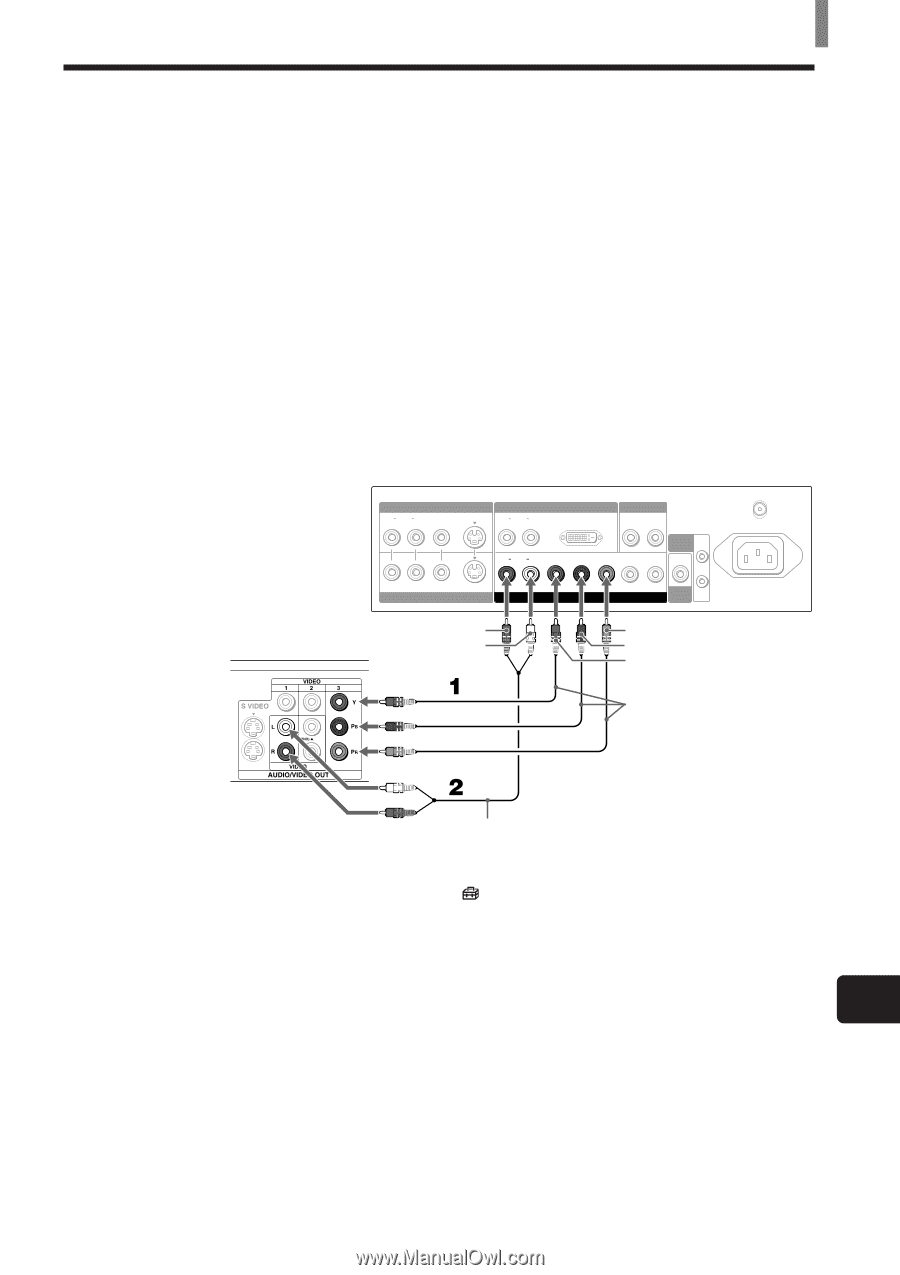
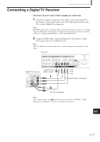
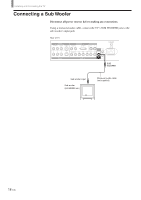
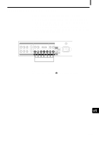
Connecting a Digital TV Receiver Installing and Connecting the TV Disconnect all power sources before making any connections. 1 Using three separate component video cables, connect the Digital TV Set-top box's Y, PB and PR jacks to the Y/G, PB/B and PR/R jacks on the TV. Use the VIDEO IN 4 connection. Note DVI-HDTV connection or component video (Y, PB, PR) connection is necessary to view 480p, 720p, and 1080i formats. Note that this TV displays all format types of picture in a resolution of 852 dots × 1024 lines (KE-32TS2U), or 1024 × 1024 (KE-42TS2U). 2 Using an AUDIO cable, connect the Digital TV Set-top box's Audio OUT jacks to the TV's AUDIO IN jacks. Note The Y, PB and PR jacks do not provide audio, so audio cables must be connected to provide sound. Rear of TV Digital TV Set-top box VIDEO IN 1 R AUDIO L VIDEO S VIDEO VIDEO IN 3 R AUDIO L DVI-HDTV AUDIO OUT R L R AUDIO L Y/G PB/B PR/R HD CONTROL S IN VD OUT VIDEO IN 2 VIDEO IN 4 SUB WOOFER AUDIO-R (red) AUDIO-L (white) PR/R PB/B Y/G VHF/UHF AC IN VMC-10HG (not supplied) RK-74A (not supplied) Note Select "Video 4 Mode" in the (Initial Setup) menu, then select "Y/PB/PR" or "RGB" depending on the Digital TV Set-top box you connect (see page 32). US (US) 17
-
 1
1 -
2
-
3
-
4
-
5
-
6
-
7
-
8
-
9
-
10
-
11
-
 12
12 -
 13
13 -
 14
14 -
 15
15 -
 16
16 -
 17
17 -
 18
18 -
 19
19 -
 20
20 -
 21
21 -
 22
22 -
23
-
24
-
25
-
26
-
27
-
28
-
29
-
30
-
31
-
32
-
33
-
34
-
35
-
36
-
37
-
38
-
39
-
40
-
41
-
42
-
43
-
44
-
45
-
46
-
47
-
48
-
49
-
50
-
51
-
52
-
53
-
54
-
55
-
56
-
57
-
58
-
59
-
60
-
61
-
62
-
63
-
64
-
65
-
66
-
67
-
68
-
69
-
70
-
71
-
72
-
73
-
74
-
75
-
76
-
77
-
78
-
79
-
80
-
81
-
82
-
83
-
84
-
85
-
86
-
87
-
88
-
89
-
90
-
91
-
92
-
93
-
94
-
95
-
96
-
97
-
98
-
99
-
100
-
101
-
102
-
103
-
104
-
105
-
106
-
107
-
108
-
109
-
110
-
111
-
112
-
113
-
114
-
115
-
116
-
117
-
118
-
119
-
120
-
121
-
122
-
123
-
124
-
125
-
126
-
127
-
128
-
129
-
130
-
131
-
132
-
133
-
134
-
135
-
136
-
137
-
138
-
139
-
140
-
141
-
142
-
143
-
144
-
145
-
146
-
147
-
148
-
149
-
150
-
151
-
152
-
153
-
154
-
155
-
156
-
157
-
158
-
159
-
160
-
161
-
162
-
163
-
164
-
165
-
166
-
167
-
168
-
169
-
170
-
171
-
172
-
173
-
174
-
175
-
176
-
177
-
178
-
179
-
180
-
181
-
182
-
183
-
184
-
185
-
186
-
187
-
188
 |
 |