Sony KE-42TS2U Operating Instructions - Page 7
Connector Types - dvi
 |
View all Sony KE-42TS2U manuals
Add to My Manuals
Save this manual to your list of manuals |
Page 7 highlights
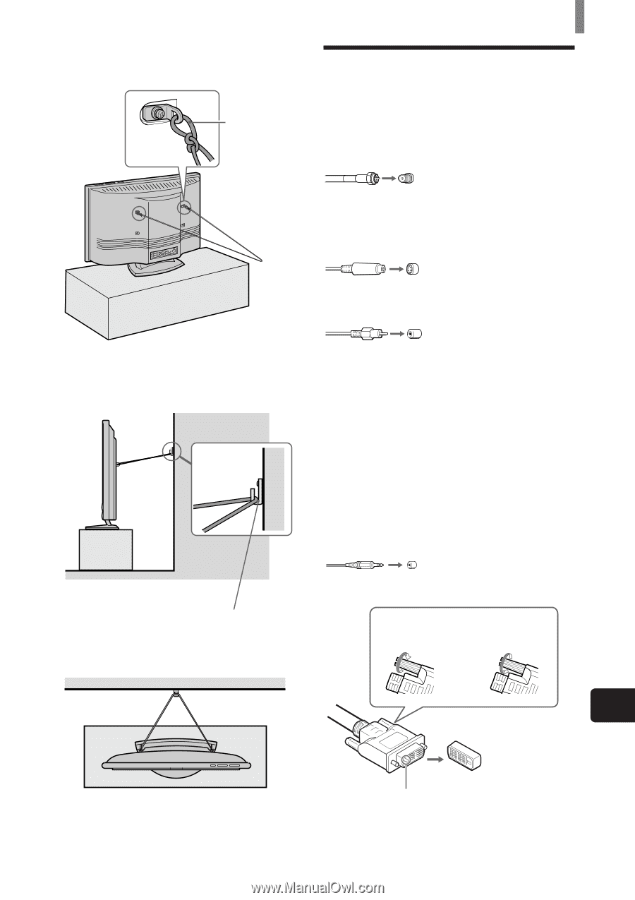
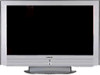
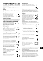
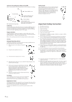
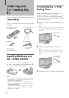
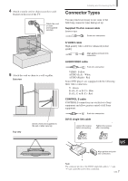
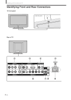
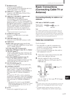
4 Attach a sturdy cord or chain securely to each bracket on the rear of the TV. Attach the cord or chain (not supplied) securely. 5 Attach the cord or chain to a wall or pillar. Side view Top view Screw a hook (not supplied) to the wall or pillar securely. Installing and Connecting the TV Connector Types You may find it necessary to use some of the following connector types during set up. Supplied 75-ohm coaxial cable Screw-on type Screw into connection. S VIDEO cable High quality video cable for enhanced picture quality Align guides and push into connection. AUDIO/VIDEO cable Push into connection. VIDEO- Yellow AUDIO (Left) - White AUDIO (Right) - Red Some DVD players are equipped with the following three video connectors: Y - Green PB (CB, Cb or B-Y) - Blue PR (CR, Cr or R-Y) - Red CONTROL S cable CONTROL S connections are exclusive to Sony equipment and allow greater control of all Sony equipment. Push into connection. DVI-D single link cable Loosen the screws before connecting. Tighten the screws after connecting. US Align guides and push into connection. A Note The connector pin (A) of the DVI-D single link cable is "-" type. "+" type cannot be used for this connection. 7 (US)
-
 1
1 -
 2
2 -
 3
3 -
 4
4 -
 5
5 -
 6
6 -
 7
7 -
 8
8 -
 9
9 -
 10
10 -
 11
11 -
 12
12 -
13
-
14
-
15
-
16
-
17
-
18
-
19
-
20
-
21
-
22
-
23
-
24
-
25
-
26
-
27
-
28
-
29
-
30
-
31
-
32
-
33
-
34
-
35
-
36
-
37
-
38
-
39
-
40
-
41
-
42
-
43
-
44
-
45
-
46
-
47
-
48
-
49
-
50
-
51
-
52
-
53
-
54
-
55
-
56
-
57
-
58
-
59
-
60
-
61
-
62
-
63
-
64
-
65
-
66
-
67
-
68
-
69
-
70
-
71
-
72
-
73
-
74
-
75
-
76
-
77
-
78
-
79
-
80
-
81
-
82
-
83
-
84
-
85
-
86
-
87
-
88
-
89
-
90
-
91
-
92
-
93
-
94
-
95
-
96
-
97
-
98
-
99
-
100
-
101
-
102
-
103
-
104
-
105
-
106
-
107
-
108
-
109
-
110
-
111
-
112
-
113
-
114
-
115
-
116
-
117
-
118
-
119
-
120
-
121
-
122
-
123
-
124
-
125
-
126
-
127
-
128
-
129
-
130
-
131
-
132
-
133
-
134
-
135
-
136
-
137
-
138
-
139
-
140
-
141
-
142
-
143
-
144
-
145
-
146
-
147
-
148
-
149
-
150
-
151
-
152
-
153
-
154
-
155
-
156
-
157
-
158
-
159
-
160
-
161
-
162
-
163
-
164
-
165
-
166
-
167
-
168
-
169
-
170
-
171
-
172
-
173
-
174
-
175
-
176
-
177
-
178
-
179
-
180
-
181
-
182
-
183
-
184
-
185
-
186
-
187
-
188
 |
 |