Sony KZ-42TS1U Operating Instructions - Page 12
Connecting a DVD Player with Component Video, Connectors
 |
View all Sony KZ-42TS1U manuals
Add to My Manuals
Save this manual to your list of manuals |
Page 12 highlights
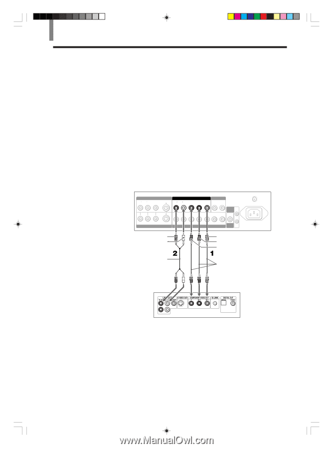
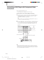
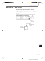
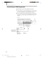
Installing and Connecting the TV Connecting a DVD Player with Component Video Connectors This is the preferred hookup to use if: • Your DVD player has component (Y, B-Y, R-Y) jacks. Disconnect all power sources before making any connections. 1 Using three separate component video cables, connect the DVD player's Y, B-Y and R-Y jacks to the Y, PB and PR jacks on the TV. Use the COMPONENT VIDEO IN 1 connections. Tip The Y, B-Y and R-Y jacks on your DVD player are sometimes labeled Y, CB and CR, or Y, PB and PR. If so, connect the cables to like colors. 2 Using an AUDIO cable, connect the DVD player's AUDIO OUT jacks to the TV's AUDIO IN jacks. Be sure to use the same row of inputs that you used for the video connection (COMPONENT VIDEO IN 1 or 2). Rear of TV VIDEO IN 1 R AUDIO L VIDEO S VIDEO COMPONENT VIDEO IN 1 AUDIO OUT R AUDIO L Y PB PR R L R AUDIO L Y/G PB/B PR/R HD CONTROL S IN VD OUT VIDEO IN 2 COMPONENT VIDEO IN 2 / RGB IN SUB WOOFER AUDIO-R (red) PR AUDIO-L (white) PB Y VHF/UHF AC IN RK-74A (not supplied) VMC-10HG (not supplied) DVD player Tips • To take advantage of the Wide Screen Modes, set the TV's aspect ratio to 16:9 on your DVD player. For details, refer to the operating instructions supplied with your DVD player. • Some DVD players are equipped with the three component video connectors; Y-Green, PB (CB, Cb or B-Y) -Blue and PB (CR, Cr or R-Y) -Red. 12 (US) 01US04CON-UC(8-19).p65 12 KZ-32/42TS1U 4-087-364-13 (1) 2002.6.22, 3:13 PM
-
 1
1 -
2
-
3
-
4
-
5
-
6
-
 7
7 -
 8
8 -
 9
9 -
 10
10 -
 11
11 -
 12
12 -
 13
13 -
 14
14 -
 15
15 -
 16
16 -
 17
17 -
18
-
19
-
20
-
21
-
22
-
23
-
24
-
25
-
26
-
27
-
28
-
29
-
30
-
31
-
32
-
33
-
34
-
35
-
36
-
37
-
38
-
39
-
40
-
41
-
42
-
43
-
44
-
45
-
46
-
47
-
48
-
49
-
50
-
51
-
52
-
53
-
54
-
55
-
56
-
57
-
58
-
59
-
60
-
61
-
62
-
63
-
64
-
65
-
66
-
67
-
68
-
69
-
70
-
71
-
72
-
73
-
74
-
75
-
76
-
77
-
78
-
79
-
80
-
81
-
82
-
83
-
84
-
85
-
86
-
87
-
88
-
89
-
90
-
91
-
92
-
93
-
94
-
95
-
96
-
97
-
98
-
99
-
100
-
101
-
102
-
103
-
104
-
105
-
106
-
107
-
108
-
109
-
110
-
111
-
112
-
113
-
114
-
115
-
116
-
117
-
118
-
119
-
120
-
121
-
122
-
123
-
124
-
125
-
126
-
127
-
128
-
129
-
130
-
131
-
132
-
133
-
134
-
135
-
136
-
137
-
138
-
139
-
140
-
141
-
142
-
143
-
144
-
145
-
146
-
147
-
148
-
149
-
150
-
151
-
152
-
153
-
154
-
155
-
156
-
157
-
158
-
159
-
160
-
161
-
162
-
163
-
164
-
165
-
166
-
167
-
168
-
169
-
170
-
171
-
172
-
173
-
174
-
175
 |
 |