Sony PZW-4000 Operating Instructions - Page 12
Rear Panel
 |
View all Sony PZW-4000 manuals
Add to My Manuals
Save this manual to your list of manuals |
Page 12 highlights
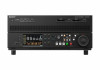
01020 2. Name and Function of Parts Rear Panel 1 2 34 5 6 7 8 9 10 11 1 9 2 10 3 4 5 6 7 8 IN IN 1 2 3 4 OUT 1 2 3 4 SYSTEM REF.VIDEO TIME CODE TC IN REMOTE 1/2 3/4 5/6 7/8 1 2 3 4 R L ANALOG AUDIO INPUT ANALOG AUDIO MONITOR B A 1 1/2 3/4 5/6 7/8 2 1/2 3/4 5/6 7/8 3 4 1/2 3/4 5/6 7/8 1/2 3/4 5/6 7/8 DIGITAL AUDIO (AES/EBU) MAINTENANCE 12 13 14 15 16 17 1. PCIe expansion slot Use to install the PZWK-4030F (option). 1) After installation, set maintenance menu item M14: OPTION SETTING >OPT BOARD to "10GbE". 2) 1) For details, refer to the PZW-4000 Installation Manual. 2) Cannot be used at the same time as the network connector (RJ-45 type) of the unit. 2. 3G-SDI dedicated expansion slot Reserved for future use. 3. SDI OUTPUT connectors (BNC type) The output signal is set using maintenance menu item M23: P2 SDI5-8. When QFHD 12G×1 is selected ˎˎ12G-SDI OUTPUT: Outputs 12G-SDI video/audio signal from SDI connector 5. ˎˎ12G-SDI MONITOR OUTPUT: Outputs 12G-SDI video/audio monitor signal from SDI connector 6. When QFHD 3G×4 SQD LvA, QFHD 3G×4 SQD LvB, QFHD 3G×4 2SI LvA, or QFHD 3G×4 2SI LvB is selected ˎˎ3G-SDI OUTPUT: Outputs video/audio signals in 3G-SDI×4 format from SDI connectors 5 to 8. 4. SDI INPUT connectors (BNC type) The input signal is set using maintenance menu item M21: P1 SDI1-4. When QFHD 12G×1 is selected ˎˎ12G-SDI INPUT: Inputs 12G-SDI video/audio signal on SDI connector 1. ˎˎ12G-SDI REC MONITOR OUTPUT: Outputs 12G-SDI video/audio monitor signal that is input on an SDI connector from SDI connector 2. When QFHD 3G×4 SQD LvA, QFHD 3G×4 SQD LvB, QFHD 3G×4 2SI LvA, or QFHD 3G×4 2SI LvB is selected ˎˎ3G-SDI OUTPUT: Inputs video/audio signals in 3G-SDI×4 format on SDI connectors 1 to 4. The number of channels of audio signals for recording can be set to 8 channels or 16 channels using maintenance menu item M371: REC CH. 5. 3G-SDI MONITOR OUTPUT connectors Recording port (SDI connector 9) and playback port (SDI connector 10 monitor outputs. The output signal is set using maintenance menu item M22: P1 SDI9 and M24: P2 SDI10. 6. Analog audio signal input/output block ANALOG AUDIO INPUT 1, 2, 3, 4 connectors (XLR 3-pin, female) Input analog audio signals. You can assign the following input signals to each connector by setting F2: AU INPUT (page 23) >A1 IN to A16 IN to "ANALOG1" to "ANALOG4" on the HOME page of the function menu. When 16 channels is selected ˎˎConnector 1: Audio channels 1, 5, 9, 13 ˎˎConnector 2: Audio channels 2, 6, 10, 14 ˎˎConnector 3: Audio channels 3, 7, 11, 15 ˎˎConnector 4: Audio channels 4, 8, 12, 16 When 8 channels is selected ˎˎConnector 1: Audio channels 1, 5 ˎˎConnector 2: Audio channels 2, 6 ˎˎConnector 3: Audio channels 3, 7 ˎˎConnector 4: Audio channels 4, 8 You can set the reference input level using maintenance menu item M373: IN LEVEL (page 71) (factory default setting: +4dB). Connectors 1 and 2 can be used as inputs and connectors 3 and 4 can be used as outputs by setting maintenance menu item M374: ANALOG I/O to "2CH IN/OUT" (page 71). In this mode, you can assign the following input signals to each connector by setting F2: AU INPUT >A1 IN to A8 IN (page 23) to "ANALOG1" or "ANALOG2" on the HOME page of the function menu. When 16 channels is selected ˎˎConnector 1: Audio channels 1, 3, 5, 7, 9, 11, 13, 15 ˎˎConnector 2: Audio channels 2, 4, 6, 8, 10, 12, 14, 16 When 8 channels is selected ˎˎConnector 1: Audio channels 1, 3, 5, 7 ˎˎConnector 2: Audio channels 2, 4, 6, 8 In this mode, you can also set the reference input level using maintenance menu item M373: IN LEVEL (page 71) (factory default setting: +4dB). When connectors 3 and 4 are configured as outputs, you can select audio tracks 1/2, tracks 3/4, tracks 5/6, tracks 7/8, tracks 9/10, tracks 11/12, tracks 13/14, or tracks 15/16 using setup menu item 824 ANALOG LINE OUTPUT SELECT (page 68) (factory default setting: tracks 1/2). You can set the reference output level using maintenance menu item M377: OUT LEVEL (page 71) (factory default setting: +4dB). ANALOG AUDIO MONITOR R, L connectors (XLR 3-pin, male) The audio signals for the channels selected using F2: MONITR L and F3: MONITR R (page 25) on the P1 AUDIO page of the function menu are output. The output signals are E-E signals or playback signals according to the REC PORT button and PB PORT button on the front panel. 7. REF. VIDEO INPUT (reference video signal input) connectors (BNC type) The two connectors form a loop-through connection. When a reference video signal is input on the IN connector (top), the same signal is input to the device connected to the connector (bottom). When no connection is made to the bottom connector, it is automatically terminated with an impedance of 75 Ω. 8. TIME CODE IN/OUT connectors IN 1 connector (BNC type): Input an SMPTE timecode signal generated by an external device. OUT 1 connector (BNC type): Pass-through output from IN 1 connector. OUT 2 connector (BNC type): Output the playback timecode signal. IN 2 to 4, OUT 3, 4 connectors: Reserved for future use.
-
 1
1 -
2
-
3
-
4
-
5
-
6
-
 7
7 -
 8
8 -
 9
9 -
 10
10 -
 11
11 -
 12
12 -
 13
13 -
 14
14 -
 15
15 -
 16
16 -
 17
17 -
18
-
19
-
20
-
21
-
22
-
23
-
24
-
25
-
26
-
27
-
28
-
29
-
30
-
31
-
32
-
33
-
34
-
35
-
36
-
37
-
38
-
39
-
40
-
41
-
42
-
43
-
44
-
45
-
46
-
47
-
48
-
49
-
50
-
51
-
52
-
53
-
54
-
55
-
56
-
57
-
58
-
59
-
60
-
61
-
62
-
63
-
64
-
65
-
66
-
67
-
68
-
69
-
70
-
71
-
72
-
73
-
74
-
75
-
76
-
77
-
78
-
79
-
80
-
81
-
82
-
83
-
84
-
85
-
86
-
87
 |
 |
