Sony STR-DE1015G Operating Instructions - Page 8
Audio, Component, Hookups
 |
View all Sony STR-DE1015G manuals
Add to My Manuals
Save this manual to your list of manuals |
Page 8 highlights
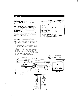
Hooking Up the System Audio Component Hookups You can use the receiver a.,s an amplifier by completing these connections. If your components are Sony products, connect them to the jacks as shown in the table on page 19 so that the IR registration is unnecessary. Note for STR-DE1015G For digital connections see "Digital Component Hookups" (page 13). S-LINK/CTRL Al ©d© (DC),© @COC, a 4O©OO 0 PHONO 0 CD 0 DAT/MD 0 TAPE What cords will I need? Audio cord (not supplied) White (L) Red (R) White (L) Red (R) : signal flow 0 CD (to CD player) Receiver CD player OU PU CD 0 TAPE (to a tape deck) Receiver COu Tape deck OU T DAT/MD (to DAT/MD deck) Receiver GOUT DAT/MD OUTPUT DAT / D PHONO (to a turntable)* Receiver Turntable OUTPUT If your turntable has an earth lead, connect it to rh SIGNAL GND on the unit to prevent hum. .c. To use Sony components with a CONTROL Al terminal You can connect a CONTROL Al compatible Sony CD player, tape deck or MD deck to the receiver. Use a CONTROL Al cord (not supplied) to connect the CTRL Al jack on each component to the S-LINK CTRL Al jack on the receiver. See the instructions for each component. y You can display the operating status of the component connected to the CTRL Al jack See page 58 for DTR-DE1015G. See page 59 for STR-DE815G. 9 To use a Sony CD changer with a COMMAND MODE selector • If the changer does not have a VIDEO OUT jack, set the command mode to "CD 1" and connect the changer to the CD jack on the receiver. • If the changer has a VIDEO OUT jack, set the command mode to "CD 2" and connect the changer to the VIDEO 1, VIDEO 2, or LD jack on the receiver. TAPE 8
-
 1
1 -
2
-
 3
3 -
 4
4 -
 5
5 -
 6
6 -
 7
7 -
 8
8 -
 9
9 -
 10
10 -
 11
11 -
 12
12 -
 13
13 -
14
-
15
-
16
-
17
-
18
-
19
-
20
-
21
-
22
-
23
-
24
-
25
-
26
-
27
-
28
-
29
-
30
-
31
-
32
-
33
-
34
-
35
-
36
-
37
-
38
-
39
-
40
-
41
-
42
-
43
-
44
-
45
-
46
-
47
-
48
-
49
-
50
-
51
-
52
-
53
-
54
-
55
-
56
-
57
-
58
-
59
-
60
-
61
-
62
-
63
-
64
-
65
 |
 |
