Stihl FS 110 Product Instruction Manual - Page 25
Mounting the Loop Handle without, Barrier Bar, Securing the Loop Handle
 |
View all Stihl FS 110 manuals
Add to My Manuals
Save this manual to your list of manuals |
Page 25 highlights
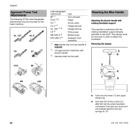
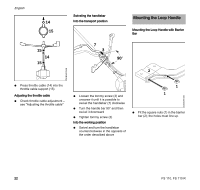
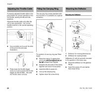
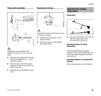
4 2 3 5 6 7 N Place the clamp (3) in the loop handle (4) and position them both against the drive tube (5). N Place the clamp (6) against the drive tube. N Place the barrier bar (2) in position as shown. N Line up the holes. N Insert the screws (7) and tighten them down moderately against the barrier bar. N Go to "Securing the Loop Handle". 002BA099 KN 002BA136 KN 002BA147 KN Mounting the Loop Handle without Barrier Bar 8 8 7 74 3 5 6 1 1 N Place the clamp (3) in the loop handle (4) and position them both against the drive tube (5). N Place the clamp (6) against the drive tube. N Line up the holes. N Fit washers (7) on the screws (8) and insert the screws in the holes. Fit the square nuts (1) and screw them down as far as stop. N Go to "Securing the Loop Handle". Securing the Loop Handle English A 9 4 10 N Secure the loop handle (4) approx. 8 in (20 cm) (A) forward of the control handle (9). N Line up the loop handle. N Tighten down the screws firmly - lock the nuts if necessary. The sleeve (10) (not fitted on all models) must be between the loop handle and the control handle. FS 110, FS 110 R 23
-
 1
1 -
2
-
3
-
4
-
5
-
6
-
7
-
8
-
9
-
10
-
11
-
12
-
13
-
14
-
15
-
16
-
17
-
18
-
19
-
 20
20 -
 21
21 -
 22
22 -
 23
23 -
 24
24 -
 25
25 -
 26
26 -
 27
27 -
 28
28 -
 29
29 -
 30
30 -
31
-
32
-
33
-
34
-
35
-
36
-
37
-
38
-
39
-
40
-
41
-
42
-
43
-
44
-
45
-
46
-
47
-
48
-
49
-
50
-
51
-
52
-
53
-
54
-
55
-
56
-
57
-
58
-
59
-
60
-
61
-
62
-
63
-
64
-
65
-
66
-
67
-
68
-
69
-
70
-
71
-
72
-
73
-
74
-
75
-
76
-
77
-
78
-
79
-
80
-
81
-
82
-
83
-
84
-
85
-
86
-
87
-
88
-
89
-
90
-
91
-
92
-
93
-
94
-
95
-
96
-
97
-
98
-
99
-
100
-
101
-
102
-
103
-
104
-
105
-
106
-
107
-
108
-
109
-
110
-
111
-
112
-
113
-
114
-
115
-
116
 |
 |
