TP-Link T2600G-52TS TL-SG3452 T2600G-52TS V1 Installation Guide - Page 23
Power On, 6 Initialization
 |
View all TP-Link T2600G-52TS TL-SG3452 manuals
Add to My Manuals
Save this manual to your list of manuals |
Page 23 highlights
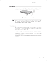
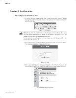
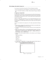
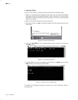
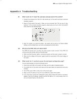
Gigabit L2 Managed Switch 4.5 Power On Plug the female connector of the provided power cord into the power socket of the device, and the male connector into a power outlet as the following figure shows. 100-240V~50/60Hz 0.5A Figure 4-6 Connecting to Power Supply Note: The figure is to illustrate the application and principle. The power cord you get from the package and the socket in your situation will comply with the regulation in your country, so they may differ from the figure above. 4.6 Initialization After the device is powered on, it begins the Power-On Self-Test. A series of tests run automatically to ensure the device functions properly. During this time, its LED indicators will respond in the following order: ■■ The PWR LED indicator lights on all the time. The SYS LED and the LED indicators of all the ports keep off. ■■ After about one minute, the SYS LED and LED indicators of all the ports will flash momentarily and then turn off. ■■ Several seconds later, the SYS LED indicator will flash, which represents a successful initialization. Connection 17
-
 1
1 -
2
-
3
-
4
-
5
-
6
-
7
-
8
-
9
-
10
-
11
-
12
-
13
-
14
-
15
-
16
-
17
-
 18
18 -
 19
19 -
 20
20 -
 21
21 -
 22
22 -
 23
23 -
 24
24 -
 25
25 -
 26
26 -
 27
27 -
 28
28 -
29
-
30
-
31
-
32
 |
 |
