Thermador VCIN54GWS Installation Instructions - Page 14
Preparing the ceiling cutout, and housing, Custom insert installation with, hood trims
 |
View all Thermador VCIN54GWS manuals
Add to My Manuals
Save this manual to your list of manuals |
Page 14 highlights
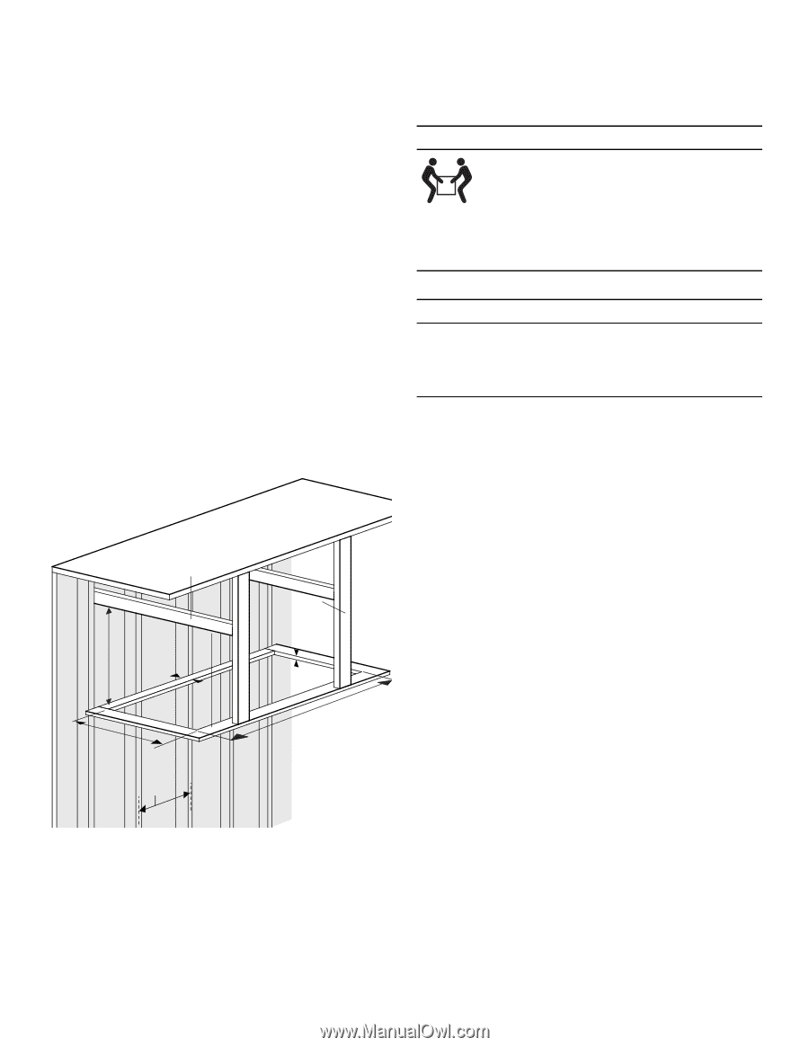
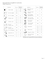
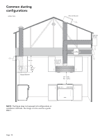
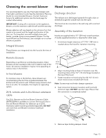
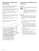
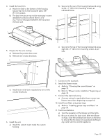
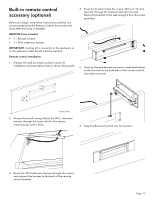
Preparing the ceiling cutout and housing Custom insert installation with hood trims The unit must be mounted to the surrounding housing. See "Installation considerations" on page 8 for suggestions on determining hood height. When calculating the load for the housing support system, be sure to include the weight of the ventilation unit. See "Unit weight" on page 8 for unit weight. Build housing in accordance with the dimensions noted in "Ceiling Cutout and Supporting Stud Housing Dimensions". For optimal performance, the hood should be mounted flush against the back wall. In such installations, the rear trim piece may not be necessary. For installations of ½'' - 3'' (13 - 76 mm) from the back wall, the rear trim piece can be used. 9 CAUTION The hood requires at least two people to lift it safely. Hidden surfaces may have sharp edges. Use caution when handling the appliance. Failure to do so may result in property damage or personal injury. 9 WARNING To avoid electrical shock hazard, before installing, switch power off at the service panel and lock the panel to prevent the power from being switched on accidentally. Ceiling Cutout and Supporting Stud Housing Dimensions inches (mm) 1½'' x 3½'' x 27-13/16'' (38 x 89 x 707) 1½'' x 3½'' x 23⅜'' (38 x 89 x 594) 12 11/ 16" (322) 0-3'' (0-76) 17 5/8" (448) ⅝'' (16) 56¼" (1,429) 1. Turn power OFF at the service panel. Lock service panel to prevent power from being turned ON. 2. Prepare the ductwork. a) Refer to "Ductwork preparation" on page 10. b) Install metal transition with backdraft damper so that the flap opens up toward the ceiling. If necessary, install thermal break and additional backdraft damper (refer to "Hood transition" on page 13). 3. Build the housing framework. a) Refer to "General information" on page 7 for the model dimensions. b) Refer to "Clearances and requirements" on page 8 for clearance specifications. c) Build housing framework for applicable model according to dimensions in "Preparing the ceiling cutout and housing" beginning on page 14. 16" (407) Page. 14
-
 1
1 -
2
-
3
-
4
-
5
-
6
-
7
-
8
-
 9
9 -
 10
10 -
 11
11 -
 12
12 -
 13
13 -
 14
14 -
 15
15 -
 16
16 -
 17
17 -
 18
18 -
 19
19 -
20
-
21
-
22
-
23
-
24
-
25
-
26
-
27
-
28
-
29
-
30
-
31
-
32
-
33
-
34
-
35
-
36
-
37
-
38
-
39
-
40
-
41
-
42
-
43
-
44
-
45
-
46
-
47
-
48
-
49
-
50
-
51
-
52
-
53
-
54
-
55
-
56
-
57
-
58
-
59
-
60
-
61
-
62
-
63
-
64
 |
 |