Thermador VCIN54GWS Installation Instructions - Page 18
Electrical wire connection, Make-up air damper relay, switch optional
 |
View all Thermador VCIN54GWS manuals
Add to My Manuals
Save this manual to your list of manuals |
Page 18 highlights
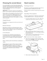
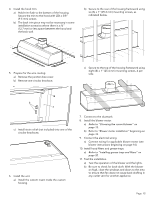
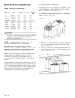
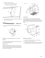
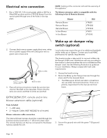
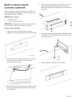
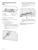
Electrical wire connection 1. Run a 120V AC, 15A circuit power cable or 20A for a PHxxGWS product and the VTR1330 blower from the service panel through one of the holes in the top plate. NOTE: Cutting of the connector will void the warranty of the appliance. The blower extension cable is compatible with the following In-line & Remote blowers: Blower Remote Blower Remote Blower Remote Blower In-line Blower In-line Blower SKU VTR630 VTR1030 VTR1330 VTI610 VTI1010 2. Connect black wire to power supply black wire, white wire to power supply white wire and green wire to green wire or bare wire. White to white Green to green or bare wire Black to black 3. Place all wiring connections inside the junction box channel. Reinstall on the top plate. Ensure that the wires are secure and that no wires are pinched. Make-up air damper relay switch (optional) Local codes may require the use of an additional backdraft and/or make-up air damper. Contact your local HVAC professional for specific requirements. This hood provides a relay switch to connect a Make-Up Air Damper (120V max). Installations will vary according to the location in the home where the unit is installed and the damper used. Use the following illustration as guidance for your installation. Always comply with local code requirements. 1. Access the hood's wiring. 2. Route the Make-up Air Damper harness through the strain relief to the terminal block. • The Make-up air kit hot and return connections can use either terminal connection. There is no polarity requirement for the two pin terminal block. EXTNCB25W 25 ft. remote and in-line blower extension cable (optional) Parts Included • 1 - 25ft cable • 2 - Adapter Cables (NOT NEEDED for all models) Blower extension cable connection The internal blower harness should be routed through the knockout and secured with a 1'' (25.4 mm) strain relief. The remote harness can then be connected to the blower harness outside the unit. 3. Secure the ground wire with the green T-20 ground screw. Page. 18
-
 1
1 -
2
-
3
-
4
-
5
-
6
-
7
-
8
-
9
-
10
-
11
-
12
-
 13
13 -
 14
14 -
 15
15 -
 16
16 -
 17
17 -
 18
18 -
 19
19 -
 20
20 -
 21
21 -
 22
22 -
 23
23 -
24
-
25
-
26
-
27
-
28
-
29
-
30
-
31
-
32
-
33
-
34
-
35
-
36
-
37
-
38
-
39
-
40
-
41
-
42
-
43
-
44
-
45
-
46
-
47
-
48
-
49
-
50
-
51
-
52
-
53
-
54
-
55
-
56
-
57
-
58
-
59
-
60
-
61
-
62
-
63
-
64
 |
 |
