Tripp Lite PDU3VSR3G60 Owner's Manual for High Voltage 3-Phase PDU 932906 - Page 8
Digital Load Meter
 |
View all Tripp Lite PDU3VSR3G60 manuals
Add to My Manuals
Save this manual to your list of manuals |
Page 8 highlights
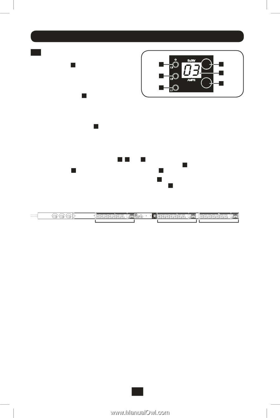
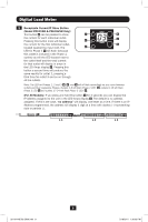
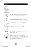
Digital Load Meter 2 Receptacle Current/IP Show Button (Model PDU3VSR & PDU3XVSR Only): This button B can be pressed to show F B the current for each individual outlet. C Pressing this button once will display E the current for the first individual outlet, A located nearest the input cord. The D LED for Phase 1 D will flash (because this outlet is included in the Phase 1 outlets) as will the LED located next to the outlet itself and the total current for that outlet will display in amps in the LED Amps display C . Pressing this button a second time will produce the same results for outlet 2, pressing a third time for outlet 3 and so on through all the outlets. Note: The LED for Phases 1, 2 and 3 D , E , and F will all flash accordingly as you move between outlets and their respective Phases. Outlets 1-8 will flash Phase 1 LED D , outlets 9-16 will flash Phase 2 LED E and outlets 17-24 will flash Phase 3 LED F . (For All Models): If you press and hold this button B for 4 seconds you can display the IP Address assigned to the unit in the LED Amps display C . The default is no address assigned. If this is the case, "no address" will display, one letter at a time. If there is an IP Address programmed, the address will display 1 digit at a time with dashes (-) representing dots or periods (.). L 1 L 2 L 3 8 201104185 93-2906.indb 8 5/18/2011 1:36:03 PM
-
 1
1 -
2
-
 3
3 -
 4
4 -
 5
5 -
 6
6 -
 7
7 -
 8
8 -
 9
9 -
 10
10 -
 11
11 -
 12
12 -
 13
13 -
14
-
15
-
16
-
17
-
18
-
19
-
20
-
21
-
22
-
23
-
24
-
25
-
26
-
27
-
28
-
29
-
30
-
31
-
32
-
33
-
34
-
35
-
36
 |
 |