Troy-Bilt Bronco CRT Service Manual - Page 13
Troy-Bilt Bronco CRT Manual
 |
View all Troy-Bilt Bronco CRT manuals
Add to My Manuals
Save this manual to your list of manuals |
Page 13 highlights
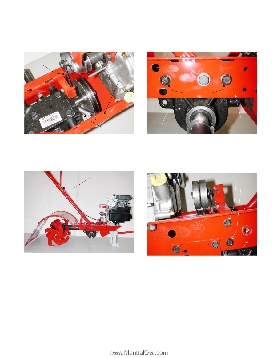
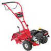
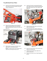
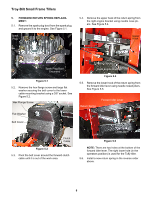
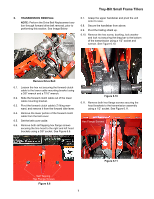
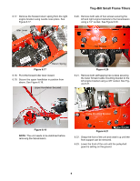
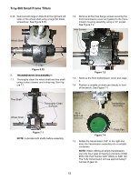
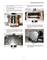
6.17. Remove the forward return spring from the right engine bracket using needle nose pliers. See Figure 6.17. Troy-Bilt Small Frame Tillers 6.20. Remove both sets of hex screws securing the left and right engine brackets to the transmission using a 1/2" socket. See Figure 6.20. Idler Lever Right Engine Bracket Hex Screws Return Spring Figure 6.17 6.18. Pivot the forward idler lever inward. 6.19. Secure the upper handlebar in position from above. See Figure 6.19. Upper Handlebar Secured Transmission Figure 6.20 Engine Bracket 6.21. Remove both self-tapping hex screws securing the lower forward cable mounting bracket to the left engine bracket using a 3/8" socket. See Figure 6.21. Self-Tapping Screws Cable Mounting Bracket Figure 6.19 NOTE: The unit needs to be stabilized before removing the transmission. Figure 6.21 Engine Bracket 6.22. Grasp the front of the unit and raise it up until the front support can be removed. 6.23. Lower the front of the unit until the pulley/belt guard is setting on the ground. 9
-
 1
1 -
2
-
3
-
4
-
5
-
6
-
7
-
 8
8 -
 9
9 -
 10
10 -
 11
11 -
 12
12 -
 13
13 -
 14
14 -
 15
15 -
 16
16 -
 17
17 -
 18
18 -
19
-
20
-
21
-
22
-
23
-
24
-
25
-
26
-
27
-
28
-
29
-
30
-
31
-
32
-
33
-
34
-
35
-
36
-
37
-
38
-
39
-
40
-
41
-
42
 |
 |