Troy-Bilt Bronco CRT Service Manual - Page 15
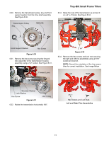
Left and Right Tine Assemblies
 |
View all Troy-Bilt Bronco CRT manuals
Add to My Manuals
Save this manual to your list of manuals |
Page 15 highlights
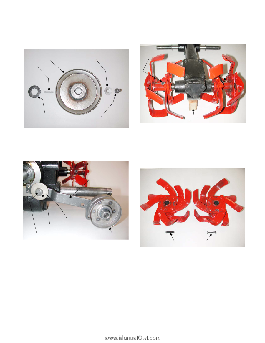
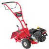
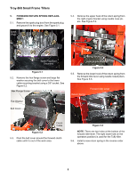
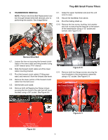
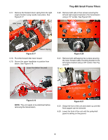
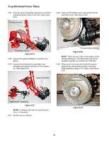
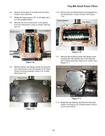
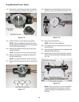
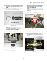
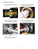
6.30. Remove the transmission pulley, key and front support washer from the drive shaft assembly. See Figure 6.30. Transmission Pulley Key Belleville Troy-Bilt Small Frame Tillers 6.33. Raise the rear of the transmission up and set it on a 2" x 4" block. See Figure 6.33. Hex Screw & Lock Nut Hex Screw & Lock Nut Front Support Washer Hex Screw Figure 6.30 6.31. Remove the hex screw securing the forward idler assembly to the transmission housing assembly using a 1/2" socket. See Figure 6.31. Forward Lever 2" x 4" Figure 6.33 6.34. Remove the hex screws and lock nuts securing the right and left tine assemblies using a 9/16" socket and wrench. NOTE: Record the orientation of the tine assemblies for correct installation. See Image Below Left Right Shoulder Washer Lock Washer Hex Screw Figure 6.31 Idler Pulley 6.32. Rotate the transmission horizontally 180°. Hex Screws and Lock Nuts Left and Right Tine Assemblies 11
-
 1
1 -
2
-
3
-
4
-
5
-
6
-
7
-
8
-
9
-
 10
10 -
 11
11 -
 12
12 -
 13
13 -
 14
14 -
 15
15 -
 16
16 -
 17
17 -
 18
18 -
 19
19 -
 20
20 -
21
-
22
-
23
-
24
-
25
-
26
-
27
-
28
-
29
-
30
-
31
-
32
-
33
-
34
-
35
-
36
-
37
-
38
-
39
-
40
-
41
-
42
 |
 |