Troy-Bilt Bronco CRT Service Manual - Page 27
Troy-Bilt Bronco CRT Manual
 |
View all Troy-Bilt Bronco CRT manuals
Add to My Manuals
Save this manual to your list of manuals |
Page 27 highlights
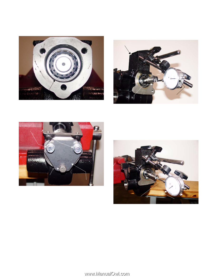
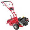
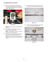
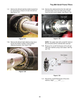
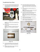
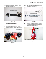
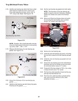
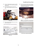
8.11. Set the rear tapered roller bearing race over the rear tapered roller bearing. See Figure 8.11. Troy-Bilt Small Frame Tillers 8.15. Pull the drive shaft assembly forward all the way, and set up a dial indicator at the front end. See Figure 8.15. Magnetic Base Rear Tapered Roller Bearing Race Figure 8.11 8.12. Set the rear bearing cap in position. See Figure 8.12. Hex Flange Screws Drive Shaft Pull Forward Zero Dial Indicator Figure 8.15 8.16. Zero the dial indicator out. 8.17. Push the drive shaft assembly rearward all the way, and record the amount of drive shaft assembly end play _____. Short Hex Flange Screw and Lock Washers Rear Bearing Cap Figure 8.12 NOTE: Do not install the bearing cap gasket. 8.13. Secure the rear bearing cap to the transmission housing with the hex flange screws removed earlier, and the miscellaneous flat washers that were located using a 1/2" socket. 8.14. Torque all of the hex screws to 100 In. Lbs using a torque wrench and a 1/2" socket. Push Drive Shaft Rearward End Play Measurement 23
-
 1
1 -
2
-
3
-
4
-
5
-
6
-
7
-
8
-
9
-
10
-
11
-
12
-
13
-
14
-
15
-
16
-
17
-
18
-
19
-
20
-
21
-
 22
22 -
 23
23 -
 24
24 -
 25
25 -
 26
26 -
 27
27 -
 28
28 -
 29
29 -
 30
30 -
 31
31 -
 32
32 -
33
-
34
-
35
-
36
-
37
-
38
-
39
-
40
-
41
-
42
 |
 |