Troy-Bilt TB30 Operation Manual - Page 13
Install The Rear Engine Cover, Installing the Hitch Plate, Connecting the Battery Cables
 |
View all Troy-Bilt TB30 manuals
Add to My Manuals
Save this manual to your list of manuals |
Page 13 highlights
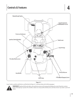
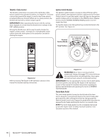
Install The Rear Engine Cover 1. Remove the two factory installed hex screws located on the rear engine cover mounting bracket. Retain the screws for later instructions. See Figure 3-10. 2. Install the rear engine cover by positioning it in place as shown in Figure 3-10. Tip the engine cover forward to fit it into the slots provided, then rotate it backwards to align the mounting holes. Connecting the Battery Cables CALIFORNIA PROPOSITION 65 WARNING: Battery posts, terminals, and related accessories contain lead and lead compounds, chemicals known to the State of California to cause cancer and reproductive harm. Wash hands after handling. CAUTION: When attaching battery cables, always connect the POSITIVE (Red) wire to its terminal first, followed by the NEGATIVE (Black) wire. For shipping reasons, both battery cables on your equipment may have been left disconnected from the terminals at the factory. To connect the battery cables, proceed as follows: NOTE: The positive battery terminal is marked Pos. (+). The negative battery terminal is marked Neg. (-). 1. Remove the factory installed hex bolts and sems nuts located on the end of the wiring harness. Retain the hardware for later instructions. 2. Remove the plastic cover, if present, from the positive battery terminal and attach the red cable to the positive battery terminal (+) with one of the bolts and hex nuts, previously removed, using a 7/16 inch wrench and socket. See Figure 3-12. Figure 3-10 3. Secure the cover with the two hex screws previously removed. Do not to over-tighten. Installing the Hitch Plate 1. Remove the factory installed hitch plate mounting hardware located on the rear of the tractor. See Figure 3-11. 2. Position the hitch plate, packed with the loose parts, with the flat side up as shown in Figure 3-11. Secure using the two bolts and hex nuts previously removed. Figure 3-11 Figure 3-12 3. Remove the plastic cover, if present, from the negative battery terminal and attach the black cable to the negative battery terminal (-) with the remaining bolt and hex nut. See Figure 3-12. 4. Position the red rubber boot over the positive battery terminal to help protect it from corrosion. NOTE: If the battery is put into service after the date shown on top/side of battery, charge the battery as instructed in the Maintenance section your Operator's Manual prior to operating the tractor. Section 3 - Assembly & Set-Up 13
-
 1
1 -
2
-
3
-
4
-
5
-
6
-
7
-
 8
8 -
 9
9 -
 10
10 -
 11
11 -
 12
12 -
 13
13 -
 14
14 -
 15
15 -
 16
16 -
 17
17 -
 18
18 -
19
-
20
-
21
-
22
-
23
-
24
-
25
-
26
-
27
-
28
-
29
-
30
-
31
-
32
-
33
-
34
-
35
-
36
-
37
-
38
-
39
-
40
-
41
-
42
-
43
-
44
-
45
-
46
-
47
-
48
-
49
-
50
-
51
-
52
-
53
-
54
-
55
-
56
-
57
-
58
-
59
-
60
-
61
-
62
-
63
-
64
-
65
-
66
-
67
-
68
-
69
-
70
-
71
-
72
 |
 |
