Uniden UM425 English Owners Manual - Page 48
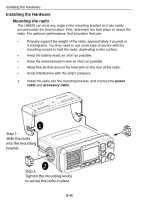
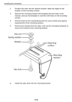
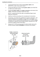
Connecting the radio - marine vhf radio
 |
UPC - 050633501221
View all Uniden UM425 manuals
Add to My Manuals
Save this manual to your list of manuals |
Page 48 highlights
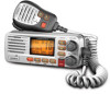
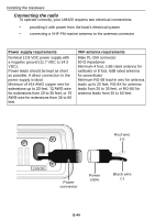
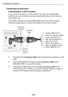
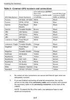
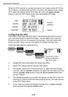
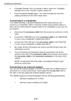
Installing the Hardware Connecting the radio To operate correctly, your UM425 requires two electrical connections: • providing it with power from the boat's electrical system • connecting a VHF-FM marine antenna to the antenna connector Power supply requirements Nominal 13.8 VDC power supply with a negative ground (11.7 VDC to 14.3 VDC). Power leads should be kept as short as possible. A direct connection to the power supply is ideal. Minimum of #14 AWG copper wire for extensions up to 20 feet, 12 AWG wire for extensions from 20 to 35 feet, or 10 AWG wire for extensions from 35 to 60 feet. VHF antenna requirements Male PL-259 connector 50 Ω impedance Minimum 4 foot, 3 dB rated antenna for sailboats or 8 foot, 6dB rated antenna for powerboats Minimum RG-58 lead-in wire for antenna leads up to 20 feet, RG-8X for antenna leads from 20 to 35 feet, or RG-8U for antenna leads from 35 to 60 feet. Red wire (+) 13.8V DC Power connector Power cable Black wire (-) E-44
-
 1
1 -
2
-
3
-
4
-
5
-
6
-
7
-
8
-
9
-
10
-
11
-
12
-
13
-
14
-
15
-
16
-
17
-
18
-
19
-
20
-
21
-
22
-
23
-
24
-
25
-
26
-
27
-
28
-
29
-
30
-
31
-
32
-
33
-
34
-
35
-
36
-
37
-
38
-
39
-
40
-
41
-
42
-
 43
43 -
 44
44 -
 45
45 -
 46
46 -
 47
47 -
 48
48 -
 49
49 -
 50
50 -
 51
51 -
 52
52 -
 53
53 -
54
-
55
-
56
-
57
-
58
-
59
-
60
-
61
-
62
-
63
-
64
-
65
-
66
-
67
-
68
-
69
-
70
-
71
-
72
-
73
-
74
-
75
-
76
-
77
-
78
-
79
-
80
-
81
-
82
-
83
-
84
-
85
-
86
-
87
-
88
-
89
-
90
-
91
-
92
-
93
-
94
-
95
-
96
-
97
-
98
-
99
-
100
-
101
-
102
-
103
-
104
-
105
-
106
-
107
-
108
-
109
-
110
-
111
-
112
-
113
-
114
-
115
-
116
-
117
-
118
-
119
-
120
-
121
-
122
-
123
-
124
-
125
-
126
-
127
-
128
-
129
-
130
-
131
-
132
-
133
-
134
-
135
-
136
-
137
-
138
-
139
-
140
-
141
-
142
-
143
-
144
-
145
-
146
-
147
-
148
-
149
-
150
-
151
-
152
-
153
-
154
-
155
-
156
-
157
-
158
-
159
-
160
-
161
-
162
-
163
-
164
-
165
-
166
-
167
-
168
-
169
-
170
-
171
-
172
-
173
-
174
-
175
-
176
-
177
-
178
-
179
-
180
-
181
-
182
-
183
-
184
-
185
-
186
-
187
-
188
-
189
-
190
-
191
-
192
-
193
-
194
-
195
-
196
-
197
-
198
-
199
-
200
-
201
-
202
-
203
-
204
-
205
-
206
-
207
-
208
-
209
-
210
-
211
-
212
-
213
-
214
-
215
-
216
-
217
-
218
-
219
-
220
 |
 |