Uniden UM425 English Owners Manual - Page 49
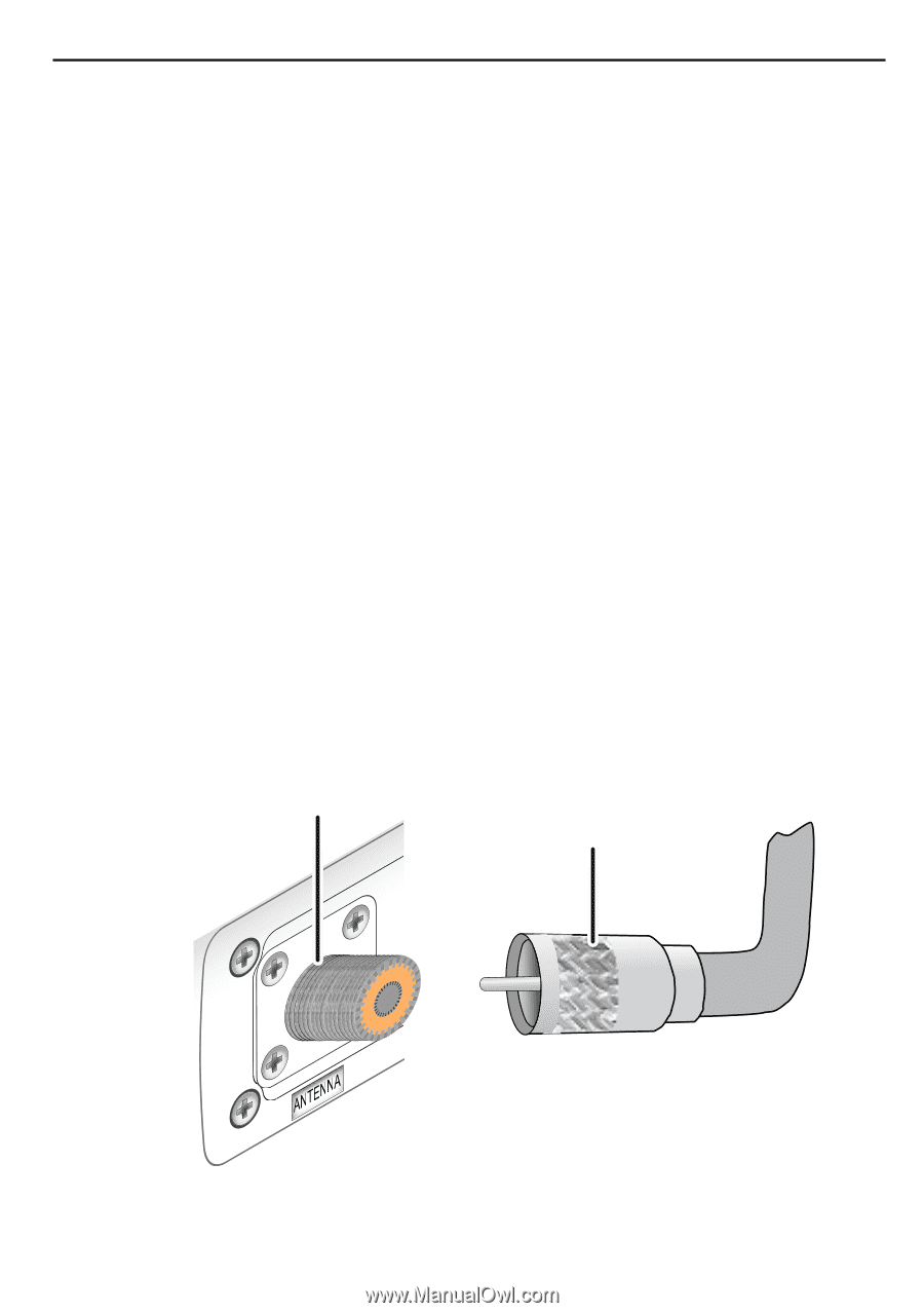
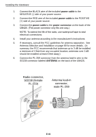
Radio connector, SO238 female, PL-259, Antenna lead-in, connector, male PL-259
 |
UPC - 050633501221
View all Uniden UM425 manuals
Add to My Manuals
Save this manual to your list of manuals |
Page 49 highlights
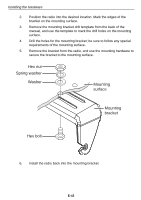
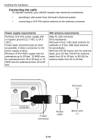
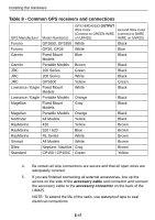
Installing the Hardware 1. Connect the BLACK wire of the included power cable to the NEGATIVE (-) side of your power source. 2. Connect the RED wire of the included power cable to the POSITIVE (+) side of your power source. 3. Connect the power cable to the power connector on the back of the UM425. (The power connector only fits one way.) NOTE: To extend the life of the radio, use waterproof tape to seal electrical connections. 4. Install your antenna according to the manufacturer's instructions. 5. If necessary, consult the FCC guidelines for antenna separation. See Antenna Selection and Installation on page 69 for more details. (In summary, the FCC recommends that antennas up to 3 dB be installed a minimum of 3 feet from any occupied location; antennas over 3 dB should be installed at least 6 feet away.) 6. Connect the PL-259 connector from the antenna lead-in wire to the SO238 connector labeled ANTENNA on the back of the UM425. Radio connector, SO238 (female PL-259) Antenna lead-in connector, male PL-259 E-45
-
 1
1 -
2
-
3
-
4
-
5
-
6
-
7
-
8
-
9
-
10
-
11
-
12
-
13
-
14
-
15
-
16
-
17
-
18
-
19
-
20
-
21
-
22
-
23
-
24
-
25
-
26
-
27
-
28
-
29
-
30
-
31
-
32
-
33
-
34
-
35
-
36
-
37
-
38
-
39
-
40
-
41
-
42
-
43
-
 44
44 -
 45
45 -
 46
46 -
 47
47 -
 48
48 -
 49
49 -
 50
50 -
 51
51 -
 52
52 -
 53
53 -
 54
54 -
55
-
56
-
57
-
58
-
59
-
60
-
61
-
62
-
63
-
64
-
65
-
66
-
67
-
68
-
69
-
70
-
71
-
72
-
73
-
74
-
75
-
76
-
77
-
78
-
79
-
80
-
81
-
82
-
83
-
84
-
85
-
86
-
87
-
88
-
89
-
90
-
91
-
92
-
93
-
94
-
95
-
96
-
97
-
98
-
99
-
100
-
101
-
102
-
103
-
104
-
105
-
106
-
107
-
108
-
109
-
110
-
111
-
112
-
113
-
114
-
115
-
116
-
117
-
118
-
119
-
120
-
121
-
122
-
123
-
124
-
125
-
126
-
127
-
128
-
129
-
130
-
131
-
132
-
133
-
134
-
135
-
136
-
137
-
138
-
139
-
140
-
141
-
142
-
143
-
144
-
145
-
146
-
147
-
148
-
149
-
150
-
151
-
152
-
153
-
154
-
155
-
156
-
157
-
158
-
159
-
160
-
161
-
162
-
163
-
164
-
165
-
166
-
167
-
168
-
169
-
170
-
171
-
172
-
173
-
174
-
175
-
176
-
177
-
178
-
179
-
180
-
181
-
182
-
183
-
184
-
185
-
186
-
187
-
188
-
189
-
190
-
191
-
192
-
193
-
194
-
195
-
196
-
197
-
198
-
199
-
200
-
201
-
202
-
203
-
204
-
205
-
206
-
207
-
208
-
209
-
210
-
211
-
212
-
213
-
214
-
215
-
216
-
217
-
218
-
219
-
220
 |
 |