Weider 150 English Manual - Page 10
Backrest, Bracket, Adjustment, oriented, shown.
 |
View all Weider 150 manuals
Add to My Manuals
Save this manual to your list of manuals |
Page 10 highlights
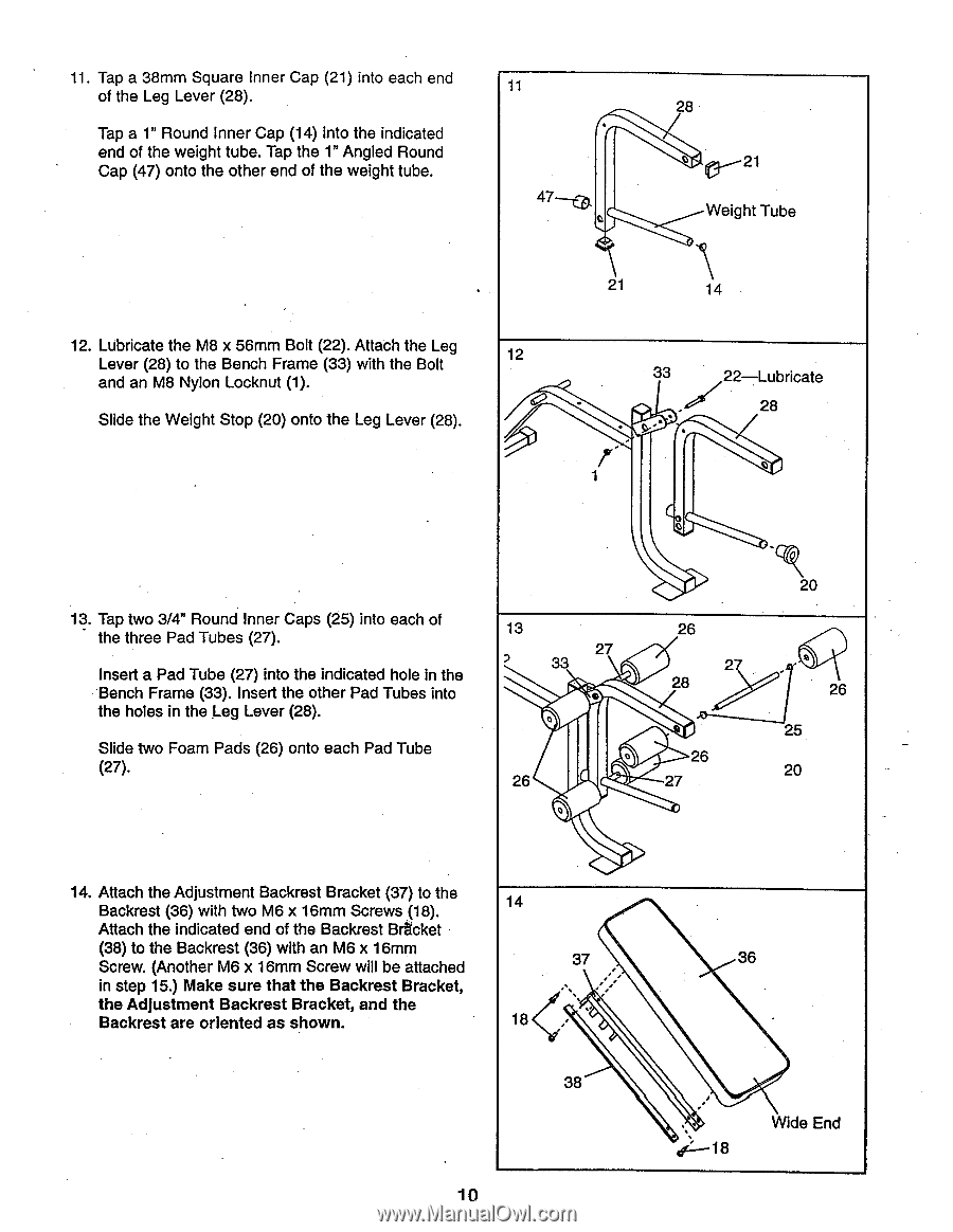
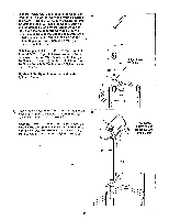
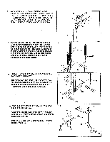
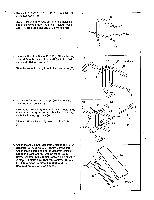
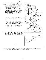
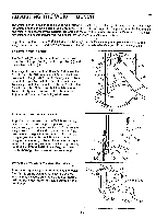
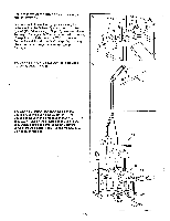
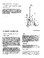
11. Tap a 38mm Square Inner Cap (21) into each end of the Leg Lever (28). Tap a 1" Round Inner Cap (14) into the indicated end of the weight tube. Tap the 1" Angled Round Cap (47) onto the other end of the weight tube. 11 47---co. o 28 o ► 21 01--- Weight Tube 21 14 12. Lubricate the M8 x 56mm Bolt (22). Attach the Leg Lever (28) to the Bench Frame (33) with the Bolt and an M8 Nylon Locknut (1). Slide the Weight Stop (20) onto the Leg Lever (28). 12 0:' ' • 33 , - s••. • 1 22-Lubricate 28 o 13. Tap two 3/4" Round Inner Caps (25) into each of the three Pad Tubes (27). Insert a Pad Tube (27) into the indicated hole in the Bench Frame (33). Insert the other Pad Tubes into the holes in the Leg Lever (28). Slide two Foam Pads (26) onto each Pad Tube (27). 13 27 2 33 o 26 27 28 0 26 26 27 20 • '' 26 25 20 14. Attach the Adjustment Backrest Bracket (37) to the Backrest (36) with two M6 x 16mm Screws (18). Attach the indicated end of the Backrest Br•acket (38) to the Backrest (36) with an M6 x 16mm Screw. (Another M6 x 16mm Screw will be attached in step 15.) Make sure that the Backrest Bracket, the Adjustment Backrest Bracket, and the Backrest are oriented as shown. 14 37 ., „ • 18 • 38 10 36 . i-•-, 18 Wide End
-
 1
1 -
2
-
3
-
4
-
 5
5 -
 6
6 -
 7
7 -
 8
8 -
 9
9 -
 10
10 -
 11
11 -
 12
12 -
 13
13 -
 14
14 -
 15
15 -
16
-
17
-
18
-
19
-
20
 |
 |