Weider 150 English Manual - Page 9
Stabilizer
 |
View all Weider 150 manuals
Add to My Manuals
Save this manual to your list of manuals |
Page 9 highlights
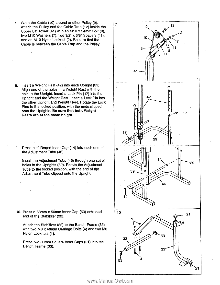
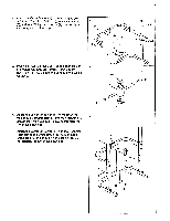
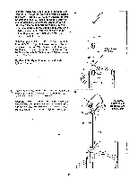
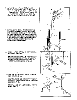
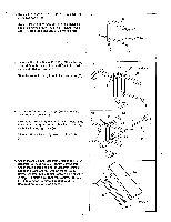
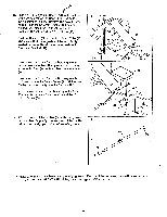
7. Wrap the Cable (10) around another Pulley (9). Attach the Pulley and the Cable Trap (12) inside the 7 Upper Lat Tower (41) with an M10 x 54mm Bolt (8), two M10 Washers (7), two 1/2" x 3/8" Spacers (11), and an M10 Nylon Locknut (2). Be sure that the Cable is between the Cable Trap and the Pulley. 9 10 8 0 12 2 -, c? ,, 11 11 41 8. Insert a Weight Rest (42) into each Upright (39). Align one of the holes in a Weight Rest with the hole in the Upright. Insert a Lock Pin (17) into the Upright and the Weight Rest. Insert a Lock Pin into the other Upright and Weight Rest. Rotate the Lock Pins to the locked position, with the ends clipped onto the Uprights. Be sure that both Weight Rests are at the same height. 8 42 . ° . . 17 ., 39 , . . . ..o.--17 . t 9. Press a 1" Round Inner Cap (14) into each end of 9 the Adjustment Tube (46). Insert the Adjustment Tube (46) through one set of holes in the Uprights (39). Rotate the Adjustment Tube to the locked position, with, the end of the Adjustment Tube clipped onto the Upright. 39 e e 14 ,,, .-- o 46 14 10. Press a 38mm x 50mm Inner Cap (53) onto each end of the Stabilizer (32). Attach the Stabilizer (32) to the Bench Frame (33) with two M8 x 48mm Carriage Bolts (4) and two M8 Nylon Locknuts (1). Press two 38mm Square Inner Caps (21) into the Bench Frame (33). 10 ........._ 1r IP 7 32 :" : . , 53 4 • gr___..--21 o 53 33 21
-
 1
1 -
2
-
3
-
 4
4 -
 5
5 -
 6
6 -
 7
7 -
 8
8 -
 9
9 -
 10
10 -
 11
11 -
 12
12 -
 13
13 -
 14
14 -
15
-
16
-
17
-
18
-
19
-
20
 |
 |