Weider 150 English Manual - Page 11
welded
 |
View all Weider 150 manuals
Add to My Manuals
Save this manual to your list of manuals |
Page 11 highlights
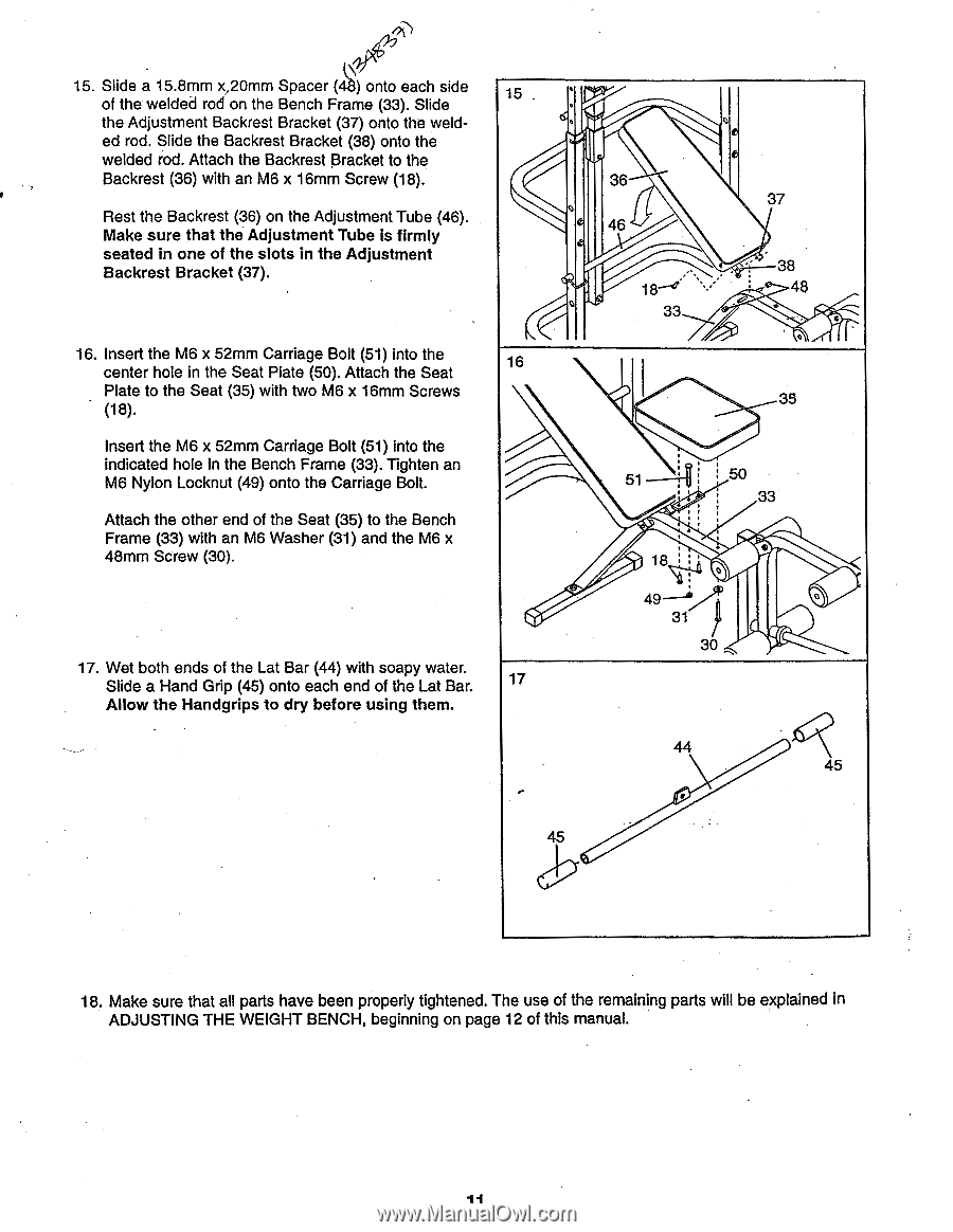
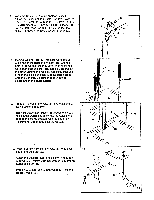
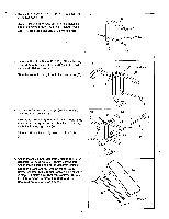
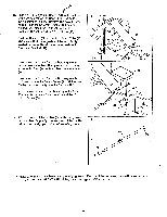
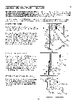
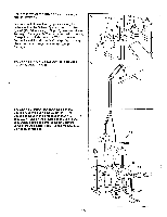
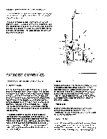
15. Slide a 15.8mm x,20mm Spacer (44) onto each side of the welded rod on the Bench Frame (33). Slide 15 the Adjustment Backrest Bracket (37) onto the weld- ed rod. Slide the Backrest Bracket (38) onto the welded rod. Attach the Backrest Bracket to the Backrest (36) with an M6 x 16mm Screw (18). Rest the Backrest (36) on the Adjustment Tube (46). Make sure that the Adjustment Tube is firmly seated in one of the slots in the Adjustment Backrest Bracket (37). 16. Insert the M6 x 52mm Carriage Bolt (51) into the center hole in the Seat Plate (50). Attach the Seat 16 Plate to the Seat (35) with two M6 x 16mm Screws (18). Insert the M6 x 52mm Carriage Bolt (51) into the indicated hole in the Bench Frame (33). Tighten an M6 Nylon Locknut (49) onto the Carriage Bolt. Attach the other end of the Seat (35) to the Bench Frame (33) with an M6 Washer (31) and the M6 x 48mm Screw (30). 17. Wet both ends of the Lat Bar (44) with soapy water. Slide a Hand Grip (45) onto each end of the Lat Bar. 17 Allow the Handgrips to dry before using them. 36 46 18-1 33 37 38 48 • 35 51 50 33 • 18 49--1 31 30 44 45 45 18. Make sure that all parts have been properly tightened. The use of the remaining parts will be explained in ADJUSTING THE WEIGHT BENCH, beginning on page 12 of this manual. 11
-
 1
1 -
2
-
3
-
4
-
5
-
 6
6 -
 7
7 -
 8
8 -
 9
9 -
 10
10 -
 11
11 -
 12
12 -
 13
13 -
 14
14 -
 15
15 -
 16
16 -
17
-
18
-
19
-
20
 |
 |