Weider 245 English Manual - Page 12
Cable Assembly, Arm Assembly
 |
View all Weider 245 manuals
Add to My Manuals
Save this manual to your list of manuals |
Page 12 highlights
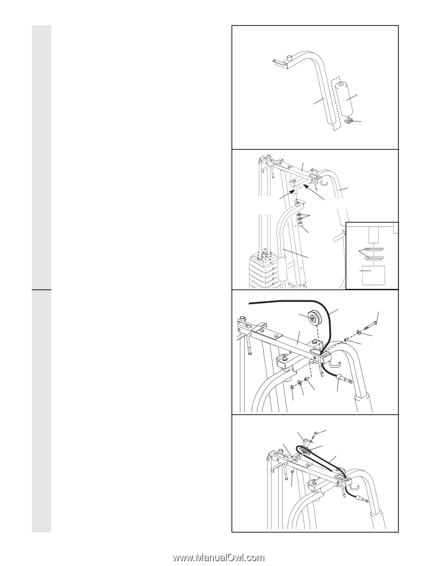
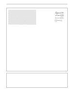
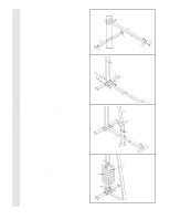
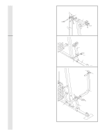
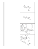
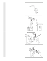
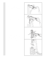
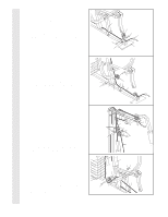
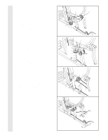
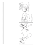
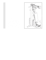
ARM ASSEMBLY 15. Press a 1 3/4" Square Inner Cap (44) into the 15 lower end of the Left Arm (47). Using a small amount of soapy water, slide a Large Foam Pad (45) onto the Left Arm. Assemble the Right Arm (48, not shown) in the same manner. 45 47 44 16. Lubricate both axles on the Top Frame (55). Slide the Right Arm (48) onto the right axle. Note: Be careful not to confuse the Right Arm with the Left Arm (47). Make sure that the upper end of the Right Arm is behind the indicated bracket on the Top Frame (55). Tap two 1" Retainers (68) and a 1" Round Outer Cap (65) onto the right axle. Make sure the teeth on the Retainers bend toward the Round Outer Cap, as shown in the inset drawing. Attach the Left Arm (47) in the same manner. 17. Important: As you assemble the cables in steps 17-30, refer to the CABLE DIAGRAM on page 21 for correct cable routing. Route the Short Cable (23) up through the hole in the Top Frame (55) as shown. Make sure the ball is on the indicated side. Attach a "V"-Pulley (6) to the hole in the Top Frame using a 3/8" x 3 1/4" Bolt (8), two 3/8" Washers (9), two 5/8" x 1/2" Spacers (82), and a 3/8" Nylon Locknut (21) as shown. Do not overtighten the Nylon Locknut; the Pulley must be able to turn freely. 18. Route the Short Cable (23) around another "V"-Pulley (6). Hold a Long Cable Trap (50) against the Pulley so that it secures the Short Cable in the groove of the Pulley. Attach the "V"-Pulley (6) and the Long Cable Trap (50) to the bracket (not shown) on the Top Frame (55) using a 3/8" x 2 1/4" Bolt (76) and a 3/8" Nylon Jamnut (67). Do not overtighten the Nylon Jamnut; the Pulley must be able to turn freely. 16 55 Lubricate Axle 47 Bracket 68 65 68 48 65 17 23 8 6 55 9 82 21 9 82 Ball 18 50 76 55 6 23 67 CABLE ASSEMBLY 12
-
 1
1 -
2
-
3
-
4
-
5
-
6
-
 7
7 -
 8
8 -
 9
9 -
 10
10 -
 11
11 -
 12
12 -
 13
13 -
 14
14 -
 15
15 -
 16
16 -
 17
17 -
18
-
19
-
20
-
21
-
22
-
23
-
24
 |
 |