Weider 245 English Manual - Page 14
Locate the Long Cable 69. Route the Long
 |
View all Weider 245 manuals
Add to My Manuals
Save this manual to your list of manuals |
Page 14 highlights
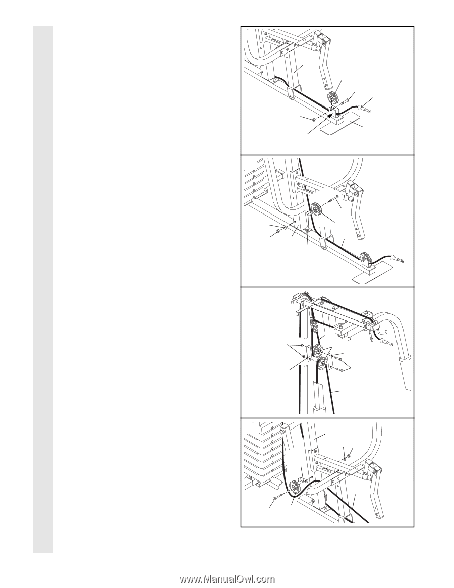
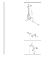
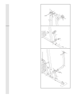
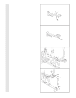
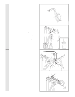
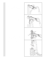
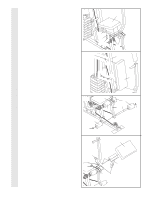
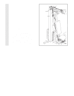
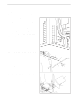
CABLE ASSEMBLY 23. Locate the Long Cable (69). Route the Long Cable between the Base (4) and the Press Frame (17) as shown. Lay the Long Cable in the bracket on the Base. Attach the Pro-Pulley (77) to the bracket using a 3/8" x 2" Bolt (12) and a 3/8" Nylon Locknut (21). Do not overtighten the Nylon Locknut; the Pulley must be able to turn freely. 24. Hold the Long Cable (69) against a 3 1/2" Pulley (15). Hold a Cable Trap (66) against the Pulley to hold the Cable in place. Attach the 3 1/2" Pulley (15) and the Cable Trap (66) to the Front Upright (42) using a 3/8" x 4 1/4" Bolt (64), a 3/8" Washer (9), and a 3/8" Nylon Locknut (21). Do not overtighten the Nylon Locknut; the Pulley must be able to turn freely. 23 17 21 Bracket 24 9 21 42 66 77 12 69 4 64 15 69 25. Remove the pre-assembled 3 1/2" Pulleys (15) from the Pulley Plates (58). Route the Short Cable (23) around one of the Pulleys. Reattach a Pulley Plate to each side of the Pulley with a 3/8" x 2" Bolt (12) and a 3/8" Nylon Locknut (21). Do not tighten the Nylon Locknut yet. Route the Long Cable (69) around the other 3 1/2" Pulley (15). Attach the Pulley to the bottom set of holes in the Pulley Plates (58) with a 3/8" x 2" Bolt (12) and a 3/8" Nylon Locknut (21). Do not overtighten the Nylon Locknuts; the Pulleys must be able to turn freely. 26. Route the Long Cable (69) around a 3 1/2" Pulley (15) as shown. Hold a Cable Trap (66) against the Pulley so that the Cable is held securely in the groove. Attach the 3 1/2" Pulley (15) and the Cable Trap (66) to the Front Upright (42) using a 3/8" x 4 1/4" Bolt (64), a 3/8" Washer (9), and a 3/8" Nylon Locknut (21). Do not overtighten the Nylon Locknut; the Pulley must be able to turn freely. 25 21 58 26 66 64 15 23 15 58 12 69 42 9 21 69 14
-
 1
1 -
2
-
3
-
4
-
5
-
6
-
7
-
8
-
 9
9 -
 10
10 -
 11
11 -
 12
12 -
 13
13 -
 14
14 -
 15
15 -
 16
16 -
 17
17 -
 18
18 -
 19
19 -
20
-
21
-
22
-
23
-
24
 |
 |