Weider 8970 Uk Manual - Page 16
Weight Resistance Chart
 |
View all Weider 8970 manuals
Add to My Manuals
Save this manual to your list of manuals |
Page 16 highlights
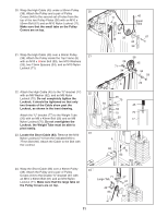
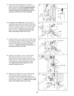
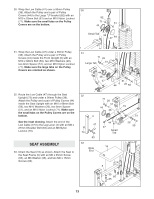
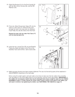
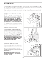
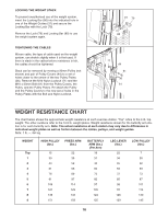
LOCKING THE WEIGHT STACK To prevent unauthorised use of the weight system, insert the Locking Bar (80) into the indicated hole in one of the Weight Guides (31) and secure the Locking Bar with the Lock (79). Remove the Lock (79) and Locking Bar (80) to use the weight system again. TIGHTENING THE CABLES Woven cable, the type of cable used on the weight system, can stretch slightly when it is first used. If there is slack in the cables before resistance is felt, the cables should be tightened. Slack can be removed by moving a 90mm Pulley (not shown) and pair of Pulley Covers (44) to a set of holes closer to the centre of the two Pulley Plates (36). Remove the M10 Nylon Locknut (71) and the M10 x 53mm Bolt (61) from the Pulley Covers, the Pulley, and the Pulley Plates. Re-attach the Pulley and the Pulley Covers to the new set of holes in the Pulley Plates with the Bolt and Nylon Locknut. 31 79 80 71 44 61 36 61 WEIGHT RESISTANCE CHART The chart below shows the approximate weight resistance at each exercise station. "Top" refers to the 6 lb. top weight. The other numbers refer to the 12.5 lb. weight plates. Weight resistance shown for the butterfly arm station is for each butterfly arm. Note: The actual resistance at each station may vary due to differences in individual weight plates as well as friction between the cables, pulleys, and weight guides. Note: 1 lb. = .454 kg WEIGHT Top 1 2 3 4 5 6 7 8 9 HIGH PULLEY PRESS ARM (lbs.) (lbs.) 15 22 30 35 44 52 61 66 76 89 91 97 106 114 121 129 136 143 151 158 BUTTERFLY ARM (lbs.) (Per Arm) 18 31 44 60 75 82 97 109 124 135 LEG LEVER (lbs.) LOW PULLEY (lbs.) 22 7 34 30 45 42 59 59 72 73 85 87 98 101 111 115 126 130 139 145 16
-
 1
1 -
2
-
3
-
4
-
5
-
6
-
7
-
8
-
9
-
10
-
 11
11 -
 12
12 -
 13
13 -
 14
14 -
 15
15 -
 16
16 -
 17
17 -
 18
18 -
 19
19 -
 20
20 -
 21
21 -
22
-
23
-
24
-
25
-
26
 |
 |
