Weider Pro 3750 User Manual - Page 9
Arm Assembly - parts
 |
View all Weider Pro 3750 manuals
Add to My Manuals
Save this manual to your list of manuals |
Page 9 highlights
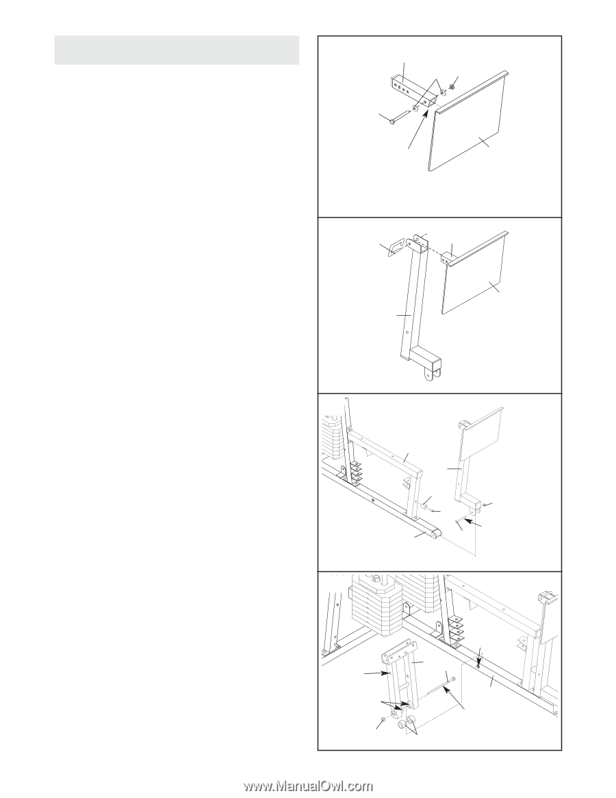
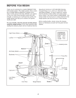
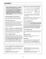
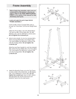
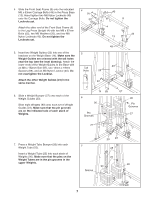
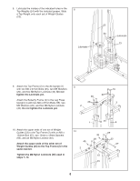
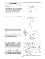
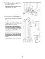
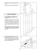
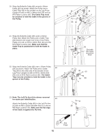
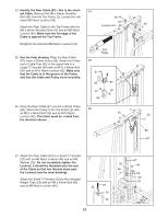
ARM ASSEMBLY 11 11. Locate and open the parts bag labeled "ARM ASSEMBLY." Attach the Leg Press Plate (11) to the Adjustment Tube (10) with an M8 x 60mm Bolt (62), two M8 Washers (20), and an M8 Nylon Locknut (40). Make sure that the Leg Press Plate and Adjustment Tube are oriented as shown. 10 20 40 62 Obtuse 11 Angle 12. Attach the Adjustment Tube (10) to the Leg Press Arm (9) with the Lock Pin (73). 12 73 10 11 9 13. Attach the Leg Press Bumper (53) to the Front 13 Seat Frame (8) with the M5 x 25mm Tap Screw (72). Lubricate the M10 x 80mm Bolt (71) with grease. Attach the Leg Press Arm (9) to the Press Base (13) with the Bolt and an M10 Nylon Locknut (42). Do not overtighten the Locknut; the Leg Press Arm must be able to pivot easily. 8 9 53 42 72 Lubricate 13 71 14. Press a 25mm x 22mm Plastic Bushing (54) onto each welded spacer on the Press Frame (12). Slide the Press Frame onto the Press Base (13) so that the Plastic Bushings are aligned with the indicated tube. Note: This will be a tight fit. Make sure that the high hole is on the side shown. Lubricate the M10 x 195mm Bolt (52) with grease. Attach the Press Frame (12) to the Press Base (13) with the Bolt and an M10 Nylon Locknut (42). Do not overtighten the Locknut; the Press Frame must be able to pivot easily. 14 High Hole Welded Spacers 42 9 12 52 Tube 13 Lubricate 54
-
 1
1 -
2
-
3
-
 4
4 -
 5
5 -
 6
6 -
 7
7 -
 8
8 -
 9
9 -
 10
10 -
 11
11 -
 12
12 -
 13
13 -
 14
14 -
15
-
16
-
17
-
18
-
19
-
20
-
21
-
22
-
23
-
24
-
25
-
26
-
27
-
28
-
29
-
30
-
31
-
32
 |
 |