Weider Pro 4900 English Manual - Page 16
Locate the Leg Lever Cable 70.
 |
View all Weider Pro 4900 manuals
Add to My Manuals
Save this manual to your list of manuals |
Page 16 highlights
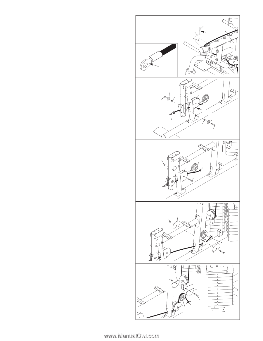
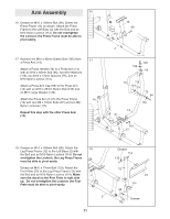
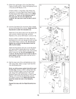
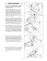
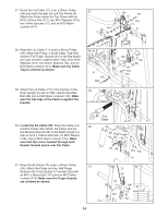
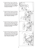
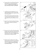
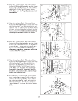
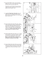
36. Grease an M8 x 22mm Shoulder Bolt (88). Attach 36 the Ab Cable (72) to the bracket on the Right Upright (4) with the Bolt and an M8 Nylon Locknut (115). Make sure the flat edge of the Cable is against the bracket on the Upright 72 115 88 4 Grease Flat Edge 37. Locate the Leg Lever Cable (70). Route the 37 Cable through the Leg Lever (11) and the Right Seat Frame (9). Make sure the Cable is over the rod in the Seat Frame. 116 75 Attach a 90mm Pulley (39) inside the Leg Lever (11), over the Leg Lever Cable (70), with an M10 x 65mm Bolt (96), two M10 Washers (116), two 12mm Spacers (75), and an M10 Nylon Locknut (114). 114 11 70 39 9 Rod 116 75 96 38. Attach a 90mm Pulley (39) inside the Right Seat 38 Frame (9), over the Leg Lever Cable (70), with an M10 x 45mm Bolt (138) and an M10 Nylon Locknut (114). 114 39 9 70 138 39. Route the Leg Lever Cable (70) through the Right 39 Upright (4) and under a 90mm Pulley (39). Attach the Pulley and two Half Finger Guards (42) to the Right Base (1) with an M10 x 48mm Bolt (101) and an M10 Nylon Locknut (114). Make sure the Finger Guards are oriented as shown. 40. Wrap the Leg Lever Cable (70) over a 90mm 40 Pulley (39). Attach the Pulley and two Half Finger Guards (42) to the Double "U"-bracket (52) with an M10 x 48mm Bolt (101) and an M10 Nylon Locknut (114). Make sure the Finger Guards are oriented as shown. 16 114 42 4 70 39 101 1 42 114 42 52 42 101 39 70
-
 1
1 -
2
-
3
-
4
-
5
-
6
-
7
-
8
-
9
-
10
-
 11
11 -
 12
12 -
 13
13 -
 14
14 -
 15
15 -
 16
16 -
 17
17 -
 18
18 -
 19
19 -
 20
20 -
 21
21 -
22
-
23
-
24
-
25
-
26
-
27
-
28
-
29
-
30
-
31
-
32
-
33
-
34
-
35
-
36
-
37
-
38
-
39
-
40
 |
 |