Weider Pro 4900 English Manual - Page 6
Frame Assembly - manual
 |
View all Weider Pro 4900 manuals
Add to My Manuals
Save this manual to your list of manuals |
Page 6 highlights
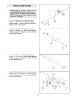
Frame Assembly 1 1. Before beginning assembly, make sure you understand the information in the box on page 5. Refer to the PART IDENTIFICATION CHART in the center of this manual for help identifying small parts. Insert four M8 x 75mm Carriage Bolts (84) up through the Right Base (1). Note: It may be helpful to place a piece of tape over the bolt heads to hold them in place. 2. Insert four M8 x 75mm Carriage Bolts (84) up 2 through the Left Base (2). Note: It may be help- ful to place a piece of tape over the bolt heads to hold them in place. 3. Insert two M8 x 75mm Carriage Bolts (84) up 3 through the Rear Base (3). Note: It may be help- ful to place a piece of tape over the bolt heads to hold them in place. 1 84 84 2 84 84 3 4. Attach the Rear Base (3) and the Left Base (2) to 4 the Right Base (1) with two M8 x 83mm Bolts (89) and two M8 Nylon Locknuts (115). Do not tight- en the Locknuts yet. 84 3 89 89 1 6 115 115 2
-
 1
1 -
 2
2 -
 3
3 -
 4
4 -
 5
5 -
 6
6 -
 7
7 -
 8
8 -
 9
9 -
 10
10 -
 11
11 -
 12
12 -
13
-
14
-
15
-
16
-
17
-
18
-
19
-
20
-
21
-
22
-
23
-
24
-
25
-
26
-
27
-
28
-
29
-
30
-
31
-
32
-
33
-
34
-
35
-
36
-
37
-
38
-
39
-
40
 |
 |
