Weider Pro 7500 Uk Manual - Page 16
Cable Assembly
 |
View all Weider Pro 7500 manuals
Add to My Manuals
Save this manual to your list of manuals |
Page 16 highlights
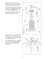
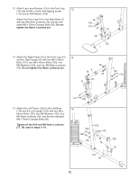
24. Apply grease to an M10 x 110mm Bolt (93). Attach the Left Press Arm (15) to the Right Press Arm (16) with the Bolt, the Spacer, and an M10 Nylon Locknut (77). Finish attaching the Press Arms (15, 16) with two M10 x 63mm Bolts (79), two M10 Washers (80), and two M10 Nylon Locknuts (77). Do not tighten the Nylon Locknuts yet. Apply grease to an M10 x 110mm Bolt (93) and a 90mm Spacer (59). Attach the Left and Right Press Arms (15, 16) to the Right Base (1) with the Bolt, the Spacer, and an M10 Nylon Locknut (77). Do not overtighten the Nylon Locknut; the Press Arms must pivot freely. Tighten the Nylon Locknuts (77) used in this step. Cable Assembly 24 16 77 77 Grease 59 1 25 59 80 77 93 25. See the CABLE DIAGRAMS on page 32 and 33 to identify the cables as you assemble them. Identify the Butterfly Cable (50). Grease an M8 x 22mm Shoulder Bolt (90). Attach the Cable to the Left Butterfly Bracket (28) with the Shoulder Bolt and an M8 Nylon Locknut (78). Make sure the flat edge of the Cable is against the Left Butterfly Bracket. Do not overtighten the Shoulder Bolt; the Cable must pivot freely. 90 Grease 50 78 28 15 93 79 Grease Flat Edge 26. Wrap the Butterfly Cable (50) over a "V"-pulley 26 (47). Attach the "V"-pulley, a Long Cable Trap (57), an M10 Washer (80), and two Guards (54) to the Right Upright (2) with an M10 x 63mm Bolt (79) and an M10 Nylon Locknut (77). 77 54 47 57 79 80 50 54 2 16
-
 1
1 -
2
-
3
-
4
-
5
-
6
-
7
-
8
-
9
-
10
-
 11
11 -
 12
12 -
 13
13 -
 14
14 -
 15
15 -
 16
16 -
 17
17 -
 18
18 -
 19
19 -
 20
20 -
 21
21 -
22
-
23
-
24
-
25
-
26
-
27
-
28
-
29
-
30
-
31
-
32
-
33
-
34
-
35
-
36
-
37
-
38
-
39
-
40
-
41
-
42
-
43
-
44
 |
 |
