Weider Pro 7500 Uk Manual - Page 8
Frame Assembly
 |
View all Weider Pro 7500 manuals
Add to My Manuals
Save this manual to your list of manuals |
Page 8 highlights
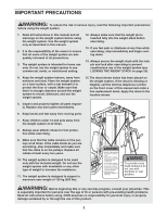
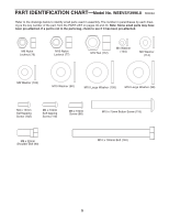
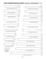
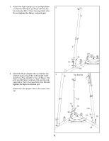
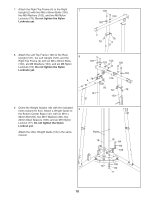
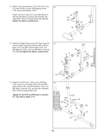
Frame Assembly 1 1. Before beginning assembly, make sure you understand the information in the box on page 7. See the PART IDENTIFICATION CHARTS on pages 5 and 6 for help identifying small parts. Insert four M8 x 75mm Carriage Bolts (83) up through the Right Base (1). Note: It may be helpful to place a piece of tape over each Bolt head to hold it in place. Apply a portion of the included grease to an M10 x 141mm Bolt (141). Attach the Foot Plate (146) to the Right Base (1) with the Bolt and an M10 Nylon Locknut (77). Do not overtighten the Nylon Locknut; the Foot Plate must pivot freely. 2. Insert six M8 x 75mm Carriage Bolts (83) up through the Left Base (119). Note: It may be helpful to place a piece of tape over each Bolt head to hold it in place. Grease 141 1 83 83 146 77 2 83 119 83 83 3. Attach the Right Base (1) to the Left Base (119) 3 with two M8 x 80mm Bolts (100), two M8 Washers (103), and two M8 Nylon Locknuts (78). Do not tighten the Nylon Locknuts yet. 78 103 100 103 78 1 119 4. Attach the Bottom Center Base (147) to the Right and Left Bases (1, 119) with four M8 x 80mm Bolts (100), four M8 Washers (103), and four M8 Nylon Locknuts (78). Do not tighten the Nylon Locknuts yet. 4 100 103 103 1 147 103 100 103 78 119 8
-
 1
1 -
2
-
 3
3 -
 4
4 -
 5
5 -
 6
6 -
 7
7 -
 8
8 -
 9
9 -
 10
10 -
 11
11 -
 12
12 -
 13
13 -
14
-
15
-
16
-
17
-
18
-
19
-
20
-
21
-
22
-
23
-
24
-
25
-
26
-
27
-
28
-
29
-
30
-
31
-
32
-
33
-
34
-
35
-
36
-
37
-
38
-
39
-
40
-
41
-
42
-
43
-
44
 |
 |
