Weslo Momentum Ct5.8 Elliptical English Manual - Page 16
Maintenance And Troubleshooting
 |
View all Weslo Momentum Ct5.8 Elliptical manuals
Add to My Manuals
Save this manual to your list of manuals |
Page 16 highlights
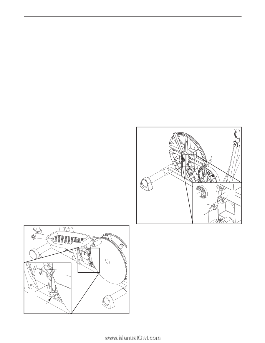
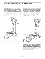
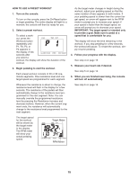
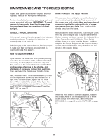
MAINTENANCE AND TROUBLESHOOTING Inspect and tighten all parts of the elliptical exerciser regularly. Replace any worn parts immediately. To clean the elliptical exerciser, use a damp cloth and a small amount of mild soap. IMPORTANT: To avoid damage to the console, keep liquids away from the console and keep the console out of direct sunlight. CONSOLE TROUBLESHOOTING If the console does not function properly, the batteries should be replaced. To replace the batteries, see assembly step 11 on page 10. If the handgrip pulse sensor does not function properly, make sure that your hands are positioned as described in step 5 on page 14. HOW TO ADJUST THE BELT If you can feel the pedals slip while you are pedaling, even when the resistance of the pedals is at the highest setting, the Belt (37) may need to be adjusted. First, remove all the screws from both shields; there are three sizes of screws in the shields-note which size of screw you remove from each hole. Then, gently pull the shields away from the frame. Next, loosen the M8 x 19mm Flat Head Bolt (61) and turn the Adjustment Screw (62) until the Belt (37) is tight. Once the Belt is tight, tighten the Flat Head Screw. Then, reattach the shields. Note: If you have questions as to which screw should be in which hole, see EXPLODED DRAWING B on page 23 and the PART LIST on page 21. HOW TO ADJUST THE REED SWITCH If the console does not display correct feedback, the reed switch should be adjusted. First, remove all of the screws from both shields; there are three sizes of screws in the shields-note which size of screw you remove from each hole. Then, gently pull the shields away from the frame. Next, locate the Reed Switch (47). Turn the Left Crank Arm (42) until a Magnet (53) is aligned with the Reed Switch. Loosen, but do not remove, the indicated M4 x 16mm Flange Screw (97). Slide the Reed Switch slightly closer to or away from the Magnet, and then retighten the Screw. Repeat until the console displays correct feedback. Note: For clarity, the discs are not shown in the drawing below. 42 53 47 97 When the reed switch is correctly adjusted, reattach the shields. Note: If you have questions as to which screw should be in which hole, see EXPLODED DRAWING B on page 23 and the PART LIST on page 21. 37 61 62 16
-
 1
1 -
2
-
3
-
4
-
5
-
6
-
7
-
8
-
9
-
10
-
 11
11 -
 12
12 -
 13
13 -
 14
14 -
 15
15 -
 16
16 -
 17
17 -
 18
18 -
 19
19 -
 20
20 -
 21
21 -
22
-
23
-
24
 |
 |