Weslo Momentum Ct5.8 Elliptical English Manual - Page 6
two M10 x 76mm Button Bolts 74, two M10 Split
 |
View all Weslo Momentum Ct5.8 Elliptical manuals
Add to My Manuals
Save this manual to your list of manuals |
Page 6 highlights
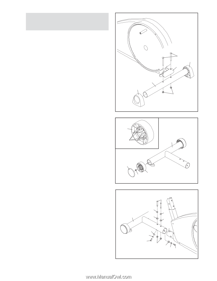
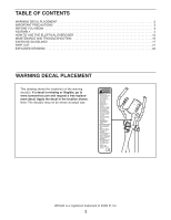
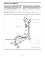
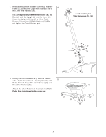
1. To make assembly easier, read the 1 information on page 5 before you begin assembling the elliptical exerciser. Attach the Rear Stabilizer (35) to the Frame (1) with two M10 x 75mm Carriage Bolts (58) and two M10 Locknuts (84). Press the Stabilizer Caps (36) onto the Rear Stabilizer (35) as shown. 35 36 58 36 1 84 2. See the inset drawing. Orient a Wheel (28) so that the four posts face away from the Front Stabilizer (3). 2 28 Attach the Wheel (28) to the Front Stabilizer (3) with an M8 Locknut (59). Next, press a Wheel Posts 3 Cover (29) onto the posts on the Wheel. Attach the other Wheel (not shown) in the same way. 29 59 28 3. Attach the Front Stabilizer (3) to the Frame (1) with 3 two M10 x 76mm Button Bolts (74), two M10 Split Washers (78), two Concave Spacers (13), and two M10 Locknuts (84). Do not tighten the Locknuts yet. Insert two M10 x 60mm Button Screws (67) with two M10 Split Washers (78) and two Concave Spacers (13) through the Front Stabilizer (3) and into the Frame (1). Tighten the M10 Locknuts (84), and then tighten the M10 x 60mm Button Screws (67). 74 78 78 3 13 13 1 13 78 67 84 13 78 67 6
-
 1
1 -
 2
2 -
 3
3 -
 4
4 -
 5
5 -
 6
6 -
 7
7 -
 8
8 -
 9
9 -
 10
10 -
 11
11 -
 12
12 -
13
-
14
-
15
-
16
-
17
-
18
-
19
-
20
-
21
-
22
-
23
-
24
 |
 |