Yamaha D24 Owner's Manual - Page 134
Terminating BNC Wordclock Distribution, Wordclock Distribution Box, Bus Distribution
 |
View all Yamaha D24 manuals
Add to My Manuals
Save this manual to your list of manuals |
Page 134 highlights
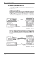
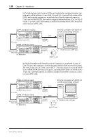
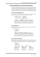
Terminating BNC Wordclock Distribution 131 Terminating BNC Wordclock Distribution When a wordclock signal is distributed via BNC cables, it must be terminated correctly. Termination is typically applied at the last device, although it depends on the distribution method being used. The D24's WORD CLOCK 75Ω TERM/THRU switch allows the D24 to be connected in a variety of ways. The following examples show three ways in which a wordclock signal can be distributed and how termination should be applied. Wordclock Distribution Box In this example, a dedicated wordclock distribution box is used to supply a wordclock signal to each device individually. Termination is applied at each device. Wordclock master WC OUT (BNC) Wordclock distribution box WC IN (BNC) Device-A Termination = ON Wordclock slave WC IN (BNC) Device-B Termination = ON Wordclock slave WC IN (BNC) Device-C Termination = ON Wordclock slave WC IN (BNC) Device-D Termination = ON Wordclock slave Bus Distribution In this example, the wordclock signal is distributed via a common bus. Termination is applied at the last device only. Wordclock master WC OUT (BNC) WC IN (BNC) Device-A Termination = ON Wordclock slave WC IN (BNC) Device-B Termination = ON Wordclock slave WC IN (BNC) Device-C Termination = ON Wordclock slave WC IN (BNC) Device-D Termination = ON Wordclock slave Daisy Chain Distribution In this example, the wordclock signal is distributed in a daisy-chain fashion, with each device feeding the wordclock signal on to the next device. Termination is applied at the last device only. This method of distribution is not recommended for larger systems. Wordclock master WC OUT (BNC) WC IN (BNC) WC OUT (BNC) Device-A Termination = OFF Wordclock slave WC IN (BNC) WC OUT (BNC) Device-B Termination = OFF Wordclock slave WC IN (BNC) Device-C Termination = ON Wordclock slave D24-Owner's Manual
-
 1
1 -
2
-
3
-
4
-
5
-
6
-
7
-
8
-
9
-
10
-
11
-
12
-
13
-
14
-
15
-
16
-
17
-
18
-
19
-
20
-
21
-
22
-
23
-
24
-
25
-
26
-
27
-
28
-
29
-
30
-
31
-
32
-
33
-
34
-
35
-
36
-
37
-
38
-
39
-
40
-
41
-
42
-
43
-
44
-
45
-
46
-
47
-
48
-
49
-
50
-
51
-
52
-
53
-
54
-
55
-
56
-
57
-
58
-
59
-
60
-
61
-
62
-
63
-
64
-
65
-
66
-
67
-
68
-
69
-
70
-
71
-
72
-
73
-
74
-
75
-
76
-
77
-
78
-
79
-
80
-
81
-
82
-
83
-
84
-
85
-
86
-
87
-
88
-
89
-
90
-
91
-
92
-
93
-
94
-
95
-
96
-
97
-
98
-
99
-
100
-
101
-
102
-
103
-
104
-
105
-
106
-
107
-
108
-
109
-
110
-
111
-
112
-
113
-
114
-
115
-
116
-
117
-
118
-
119
-
120
-
121
-
122
-
123
-
124
-
125
-
126
-
127
-
128
-
 129
129 -
 130
130 -
 131
131 -
 132
132 -
 133
133 -
 134
134 -
 135
135 -
 136
136 -
 137
137 -
 138
138 -
 139
139 -
140
-
141
-
142
-
143
-
144
-
145
-
146
-
147
-
148
-
149
-
150
-
151
-
152
-
153
-
154
-
155
-
156
-
157
-
158
-
159
-
160
-
161
-
162
-
163
-
164
-
165
-
166
-
167
-
168
-
169
-
170
-
171
-
172
-
173
-
174
-
175
-
176
-
177
-
178
-
179
-
180
-
181
-
182
-
183
-
184
-
185
-
186
-
187
-
188
-
189
-
190
-
191
-
192
-
193
-
194
-
195
-
196
-
197
-
198
-
199
-
200
-
201
-
202
-
203
-
204
-
205
-
206
-
207
-
208
-
209
-
210
-
211
 |
 |
